In “Look inside the 5G mmWave signal chain,” we explored the overall architecture of the mmWave signal chain. Now, we’ll look deeper into each of a transceiver’s components.
Phase-locked Loops (PLL) are important blocks for a clean reference clock generation in cellular networks. In 5G mmWave radio networks, the PLL supports data rates of 1 Gb/sec, with a carrier frequency starting from 24 GHz to 28 GHz, though some networks also use 39 GHz.
To generate the necessary IF carriers for transmit and receive functions, transceivers contain PLLs. A PLL is essentially a feedback system that generates a precise periodic signal at a particular frequency and phase.
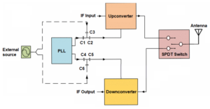
Figure 1. This transceiver module has a fixed IF at 3.5 GHz (repeated from the article, “Look inside the 5G mmWave signal chain“) showing where a PLL fits into an RF transceiver signal flow (Image: Study of 28 GHz Transceiver Module Integrated With LO Source for 5G mmWave Communication).
The PLL is employed as a local oscillator (LO), as part of the RF transceiver, in conjunction with the external supplemental source in parallel with that PLL (Figure 1).
What does a PLL do?
The PLL synchronizes the internal oscillator signal to an input reference signal, letting the signals operate at the same phase. Doing so produces a clean, stable frequency signal that is the same as the input signal, all the while providing a clean output signal with suppressed noise, less interference, and modulation. This ability enables mmWave base station designers to create a filtered version of the reference enabling control over the way the output will track that reference.
What does a PLL do for a 5G base station?
A PLL “remembers” the signal frequency should a brief interruption occur in a CW carrier or a pulsed transmission. That helps a base station recover from a lost signal during a handover. The fast master cell group (MCG) link-recovery feature, introduced in 3GPP Release 16, decreases the connection interruption time when a radio link failure (RLF) occurs. By using secondary cell group (SCG) connectivity, the interruption time caused by the MCG RLF shrinks from a few seconds down to a typical handover interruption time of 30 msec to 70 msec. This will directly translate into decreased service interruption times for end users.
The indirect form of RF frequency synthesizer, based around the PLL, is the most used form of RF synthesizer. In indirect frequency synthesis, an additional PLL circuit is employed to generate the fine-tuned frequencies. In an indirect synthesizer, the final signal gets generated, with the aid of a PLL, via an oscillator.
While maintaining the basic functionality of the PLL, additional circuitry provides the frequency synthesizer action. By employing this additional circuitry, a frequency offset is added to the loop. The synthesizer can now become either a digital synthesizer or an analog synthesizer just by introducing a digital divider or analog mixer, respectively.
Now, with this added circuitry, designers have the flexibility of easily deploying a digital or analog synthesizer to their design.
Does a PLL produce finely tuned signal frequency and phase?
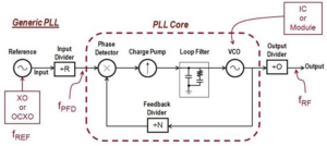
When using a PLL synthesizer within any system, the total phase noise will be composed of a collection of noise from each circuit block and component. Each component has its own contribution to the final output. Figure 2 shows the various contributing components and circuitry, including the voltage-controlled oscillator (VCO), the reference clock, and the phase-frequency detector. There are also various internal buffers, in addition to circuitry necessary to complete the PLL.
Designers will need to decide between the advantages and disadvantages of a Fractional-N PLL vs. Integer-N PLL.
Is there more than one type of PLL?
The Fractional-N PLL is a key building block in SoCs for many applications such as frequency synthesis for wireless transceivers.
The Integer-N PLL can be used as a local oscillator and clock source in communications.
In general, a Fractional-N PLL synthesizer will have some advantages over an Integer-N PLL; A Fractional-N PLL synthesizer allows for larger reference frequency values, leading to a smaller multiplier term N.
With a Fractional-N PLL synthesizer, the advantage is the smaller step size or higher resolution. A Fractional-N PLL has step sizes of tens of hertz; an Integer-N PLL may have step sizes in tens of kilohertz. The Fractional-N will lock faster compared to a similar Integer-N PLL. That’s because the lower value of N enables a wider loop filter bandwidth, which results in a quicker lock time.
One prime example is a 28 GHz Integer-N PLL, which has a very low reference frequency of 25 MHz. A Quadrature VCO running at 28 GHz is a more power-efficient design to create quadrature phases.
The only disadvantages of a Fractional-N PLL synthesizer are:
- The fractional and integer boundary spurs it generates,
- Its increased complexity from a usage standpoint (so the loop filter must be designed)
- And in some cases, a higher cost.
Analog Devices claims that its latest Fractional-N PLL mitigates the above disadvantages. This is because their designs yield very low integer boundary spurs, and their fractional divider employs an advanced 4th-order delta-sigma (ΔΣ) modulator that will not produce fractionalization spurs.
As far as complexity, the FracNWizard software has an advanced PLL design and simulation capabilities; this simplifies the loop design effort for circuit designers. In the case above, the PLL is a discrete component in 5G equipment.
Stay tuned for my next article on the 5G mmWave signal chain: The up/down converter.
References
Study of 28 GHz Transceiver Module Integrated with LO Source for 5G mmWave Communication, IEEE.
PLL for 5G mmWave LUP Student Papers.
A 27-29GHz Integer-N PLL with Quadrature phases for 5G applications, IEEE 2019.


Tell Us What You Think!