MIMO differs from LTE to 5G, plus 5G adds mmWave frequencies and beam steering. Both force changes in emulating channels.
Multiple-input/multiple-output (MIMO) transmissions gained prominence in 4G wireless as a technique to improve communication quality and reliability. MIMO uses multiple correlated antennas on both the base station and the user equipment (UE) to improve user data throughput in both directions.
5G takes MIMO to the next level by introducing higher-order MIMO at lower frequencies and beamforming in antenna arrays at higher frequencies. Testing these enhancements is critical to the core promise of 5G—massive increases in bandwidth, speed, and throughput.
First introduced with LTE, over-the-air (OTA) is a method for testing device performance and reliability in a repeatable, systematic way. OTA test involves placing the device in a chamber (Figure 1) and testing its assets—including the antenna, the RF front end, and the baseband.
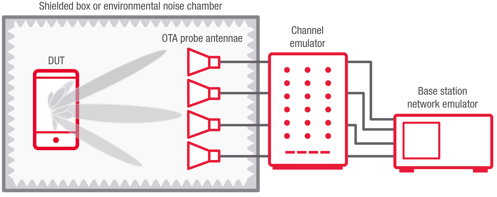
Figure 1. Over-the-air 5G radio testing requires the use of a chamber to isolate the equipment under test from outside signals and interference.
OTA testing is all-inclusive, treating the device as a composite unit. By contrast, traditional subsystem tests consider only bounded silos such as the baseband and RF signals. OTA testing requires that you include multipath effects and a device’s operating condition.
OTA testing of devices that use MIMO combines standard OTA with real-world operating conditions to perform a critical evaluation of the device’s performance. The real-world operating conditions are crucial. After all, this is where the UE must perform—not in the lab, but in the actual environment of users.
These real-world conditions can vary widely. For example, in dense urban areas, sustaining line-of-sight is difficult, and the signal reflects off many surfaces. Rural environments offer few protections. Indoor office and home environments often mean high signal blockage from walls. An effective MIMO OTA test models these conditions and presents them in a repeatable and systematic manner.
The increased complexity of 5G compared to LTE increases the difficulty of MIMO OTA testing. Massive MIMO and beamforming technologies further complicate the operation. Figure 2 shows a visualization of a beam forming capable antenna array with 64+64 antenna elements.
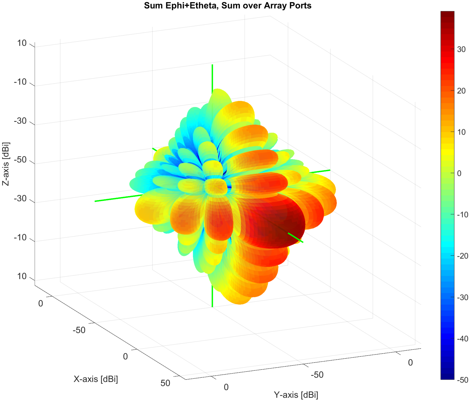
Figure 2. This visualization shows the radiating pattern from a beamforming-capable antenna array with 64×64 antenna elements.
A closer look at MIMO OTA
All major standards (such as 3GPP) and mobile-network operators mandate MIMO OTA tests for user and network equipment. A MIMO OTA test features a UE and a base station, each equipped with MIMO technology. The UE receives both line-of-sight transmissions and reflected signals from the base station. OTA testing involves the following steps.
- Isolate the device under test (DUT)—the UE—and the base station.
- Create a channel model—a model that comprises all the reflections—in between. A channel model estimates the delay between multiple parts, the angles in which the signals get transmitted and received, along with the different path loss components. The channel model is frequency-dependent, among other parameters, and varies depending upon which frequency range one operates in. A channel emulator is a lab instrument that recreates the radio conditions under which a device operates.
- Replace the base station with a network emulator to create repeatable cell signals with a defined set of parameters.
Ultimately, the channel emulator, network emulator, and a multi-probe anechoic chamber present the signals to the DUT in a pristine setup. A chamber helps isolate the DUT and perceive the signals. Together, this equipment forms a repeatable environment for MIMO OTA device evaluation.
Power delay profile
A radio-channel model is the reconstruction of an environment with reflections, delays, and path loss. In simple terms, reflected signals having similar characteristics are clustered, and each cluster has a specific time and direction. Figure 3 shows a 3D graphical representation of an OTA measurement of a transmit beam strength in equivalent isotropically radiated power (EIRP).
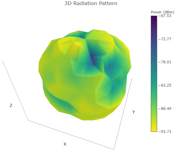
Figure 3. A 3D graph shows transmit beam strength measured in equivalent isotropically radiated power (EIRP).
In Fig. 3, direction refers to angles of departure and angles of arrival. The reflective signals arrive at different times and enter with varying levels of power as they activate due to path loss. This power profile with delays is called a power delay profile, which is mapped into the chamber as a function of time. Together, mapping this model into a chamber presents a signal at different powers and times that is power and delay. Different actions at a space recreate the radio conditions inside the lab.
It is critical to have a channel emulator along with a set of probes to perform device assessment using radio channel conditions.
MIMO OTA standards
For 5G Frequency Range 1 (FR1), 3GPP mandates a MIMO OTA setup with 16 probes and a range length of 120 cm. The structure is similar to the setup for LTE MIMO, although it deviates in some critical ways.
The first is the frequency coverage. In LTE, most of the testing was done under 2.7 GHz. Today, with 5G New Radio (NR), this frequency range extends up to 7.2 GHz. Along with the increased frequency, MIMO OTA testing for FR1 also uses different channel models. LTE had urban macro and urban micro channel models with up to six delay clusters. 3GPP’s specification 38.901 on 5G channel models specifies urban macro and urban micro-clustered delay line (CDL) channel models with 24 clusters, so they are inherently different models.
Another significant change is to MIMO order. Even though 4×4 MIMO antenna configurations support LTE, the MIMO OTA testing specifications for OTA defined testing of 2×2 MIMO configurations. By contrast, for 5G NR, the MIMO order has potential for 4×4 MIMO.
Yet another meaningful change between LTE and FR1 MIMO OTA testing is the base station antenna configuration. LTE base stations utilize a specialized cross-polarized dipole antenna. But antenna configurations on 5G base stations are much more complex. For starters, 5G massive MIMO introduces the concepts of beamforming and beam steering, and a codebook for selecting the two strongest beams. None of this existed in LTE.
Finally, LTE used only eight dual-polarized probes implemented in the chamber. But 5G FR1 uses 16 probes. This means that while the chamber infrastructure remains the same, the number of probes doubles. The test is still two-dimensional, but there are significant changes to the channel model, the MIMO order, and the base station antenna configuration. These changes necessitate new channel emulators as well as new channel models.
FR2 MIMO OTA remains a work in progress
While MIMO OTA testing for FR1 is similar to MIMO OTA testing for LTE, there is no reference basis for MIMO OTA testing for 5G’s Frequency Range 2 (FR2). The FR2 test is entirely new, requiring new assumptions that lead to a new system definition.
The channel models for FR2 have also been taken from 3GPP’s 38.901. They include an urban microchannel model and an indoor office channel mode. Both have root-mean-micro delay spreads—60 ns in the case of the urban microchannel model and 30 ns in the case of the indoor office.
The base station for the FR2 test has an 8×16 antenna array for a total of 128 fixed beams. The test setup includes six probes for FR2 MIMO OTA testing, with actual probe locations are still to be determined.
Other aspects of MIMO OTA test for FR2 are also yet to be decided. However, the underlying assumptions are in place, and there are proposals for taking the system design forward. There is a clear path to identify the next steps.
What to look for in MIMO OTA
Ultimately, the most critical aspect of 5G MIMO OTA testing is attaining reliable and consistent results. To accomplish this, it is crucial to achieve low measurement uncertainty, instrument linearity, and phase stability—both long term and between re-boots.
It is also critical that 5G MIMO OTA testing obtain fast test results and device ranking using a statistically correct method.
Finally, 5G MIMO OTA must evolve to offer higher availability and stability through round-the-clock testing, reduced calibration requirements, high phase stability, and rapid support.
 Dylan McGrath is a veteran technology journalist and former editor in chief of EE Times. He is now a senior industry solutions manager at Keysight Technologies.

At 78 years old I smile at remembering soldering a transistor into a circuit board while building my first radio whien apprenticing with Ferranti Ltd. to become an Electronic Technician. I left the industry due to lack of work when Wilson cancelled the TSR2 radar contract with America.
My comment:
Regarding our health with the electrical or magnetic fields generated by G5 Communication is this similar to a mouse running through our house being replaced by an elephant?