The next generation of cellular networks has advanced rapidly in the last year and half with the finalization of the non-standalone (NSA) and standalone (SA) New Radio (NR) specifications by the 3rd Generation Partnership Project (3GPP) organization. This, in turn, has sped up the timeline for the release of 5G chipsets and subsequently, enhanced mobile broadband (eMBB) and 5G-enabled user equipment, modems, and various devices. All major U.S. telecommunications companies have begun field trials of 5G technologies that enable gigabit speeds and low latency communications. And, while these standards have introduced a platform to generate a new string of 5G technologies, they have also established methods to effectively test 5G devices. This article grants an overview of some of the technical specifications released by 3GPP that assess the technologies that benefit from the new features of Releases 14 and 15.
Test Documents for 5G Conformance Testing
The conformance testing for 5G devices based on the recent 3GPP release 15 standard is still in being compiled by the Technical Specification Group (TSG) RAN Working Group 5 (RAN5) and Working Group 4 (RAN4) within 3GPP. The RAN WG5 will specialize in testing radio interface technologies (RIT) such as user equipment (UE), while the RAN WG4 will focus on the minimum requirements for transmission and reception parameters in base stations (BS). RIT is a term that encompasses all the technologies involved the wireless interfacing between UE and a Universal Terrestrial Radio Access Network (UTRAN) access point―a point within a UTRAN cell that performs transmission and reception. Released in October 2017, the ITU-R M.2412-0 technical report provides the guidelines for testing RITs as well as a Set of RITs (sRITs) in various test environments in order to meet the standards for IMT-2020―the vision for International Mobile Telecommunications (IMT) by 2020 and beyond. Technical specifications for testing new technologies in BS and UE released from 3GPP will be referenced including conformance testing of multi-standard radio (MSR) base stations (TS 37.141), active antenna system (AAS) BS (TR 37.842), and multi-antenna performance of UE (TR 37.977).
Defining Base Station and User Equipment Parameters
Test Environments for Radio Interface Technologies (RITs)
The ITU-R M.2412-0 document, there are essentially three usage scenarios for RITs: Enhanced Mobile Broadband (eMBB), Massive Machine Type Communications (mMTC), and Ultra-reliable and Low Latency Communications (URLLC). The term eMBB is essentially an upgrade of the current mobile broadband infrastructure, this would include LTE-A with high-order advanced modulation schemes and carrier aggregation. The eMBB application can be used in several environments including indoor hotspots, dense urban environments, and rural environments. The mMTC usage scenario involves a large number of connected devices transmitting a low volume of non-delay-sensitive data such as smart city or farming applications. The URLLC requires strict throughput, latency, and availability capabilities for critical wireless data such as industrial process, medical, automotive, and smart grid communications. Table 1 lists the usage scenarios as well as the respective carrier frequencies, maximum transmit power, and device power class of RITs/sRITs that are expected to be leveraged by IMT-2020.
|
Applications |
eMBB |
mMTC |
URLLC |
||
|
Test Environment |
Indoor Hotspot |
Dense Urban |
Rural |
Urban Macro |
Urban Macro |
|
Carrier Frequencies |
4,30, 70 GHz |
4 GHz (Macro), 30 GHz (Macro), 4+30GHz (Macro + Micro)* |
700 MHz, 4 GHz |
700 MHz |
700 MHz, 4 GHz |
|
Max Total Transmit Power per TRxP (dBm) |
24, 23, 21 |
44, 40, 44 |
49, 49 |
49 |
49,49 |
|
UE Power Class (dBm) |
23, 23, 21 |
23, 23, 23 |
23, 23 |
23 |
23,23 |
*A Macro layer is made up of either a large wide range BS, or up to three Micro layers. The micro layer can be formed with smaller, shorter ranged BSs.
Table 1: Usage scenarios and geographic environments of RITs/sRITs.
Base Station and User Equipment Antenna Structures
Base station (BS) antennas are defined by having one or multiple antenna panels, where each panel has multiple antenna elements. These elements are placed in a two-dimensional array within each panel forming a large active antenna system (AAS) with hundreds to thousands of elements.
Antenna architectures for UEs are likely singular omni-directional antenna elements within the 700 MHz and 4 GHz. The higher millimeter-wave (mmWave) frequencies (30 & 40 GHz) assume a panel of directional antenna elements where each element may have different orientations and can therefore radiation in various directions.
Channel Modeling
Along with some physical baseline parameters defined for new generation RITs, it is critical that they be tested with highly developed test environment simulations. The ITU-R M.2412-0 report lists a number of channel models as well as their respective configuration parameters to allow for realistic modelling of the propagation conditions in these various environments. New features are constantly being developed by a number of organizations including 3GPP, Mobile and wireless communications Enabler for the Twenty-twenty Information Society (METIS), Millimetre-wave Evolution for Backhaul and Access (MiWEBA), COST2100, IEEE802.11, and 5G Promotion Association in China. These new features include support for frequencies up to 100 GHz, large bandwidths, 3D modeling, and antenna array support. Three-dimensional modeling, for instance, enables both azimuth and elevation plane measurements for OTA test setups potentially providing valuable additional information about the device under test (DUT). As 4G technologies advanced and 5G devices are implemented, channel models must respectively evolve to adequately simulate a realistic test environment.
Base station Classes
There are three base station classes as specified in both the Multi-Standard Radio (MSR) Base Station (BS) conformance testing and the Radio Frequency (RF) requirement background for Active Antenna System (AAS) Base Station (BS) documents. These classes are listed in Table 2, where the manufacturer is responsible for stating the intended class of the BS under test.
|
BS Classes |
Usage Scenario |
Minimum Coupling Loss |
AAS Base Station Rated Output Power |
Maximum Directional Gain of Antenna Element |
|
Wide Area BS |
Macro Cell |
70 dB |
N/A |
8 dBi |
|
Medium Range BS |
Micro Cell |
53 dB |
< 38 dBm |
5 dBi |
|
Local Area BS |
Pico Cell |
45 dB |
< 24 dBm |
5 dBi |
Table 2: BS Classes.
Base Station Tests
While there are a number of tests for base stations transmitters and receivers, including Time Alignment Error (TAE), Adjacent Channel Leakage Ratio (ACLR), Intermodulation, and Unwanted Emissions, some specifications must be declared by manufacturers including Equivalent Isotropically Radiated Power (EIRP) and minimum Effective Isotropic Sensitivity (EIS).
Equivalent Isotropically Radiated Power (EIRP)
The EIRP is the total power that an ideal isotropic antenna would have to put out to provide the same signal strength as the Antenna Under Test (AUT) in the direction of the AUT’s strongest beam. Test for EIRP can be accomplished in an anechoic chamber with a standard mirror feed horn, or with a reflector and feed antenna for the Compact Antenna Test Range (CATR) measurement, as well as with one-dimensional probe. Figure 1 depicts the standard test setup for EIRP where the calibration within the chamber can be accomplished with a Vector Network Analyzer’s (VNAs) RF out port attached to the reference antenna and the RF in port to the receiving antenna. The VNA can then take into account the path loss due to the environment and cable loss due to the attached coax. The AAS BS under test can then be placed in the chamber and rotated to be in alignment with the receiving antenna. The EIRP can then be measured by transmitting a signal at maximum power and measuring the mean power for each carrier arriving at the measurement equipment’s connector.
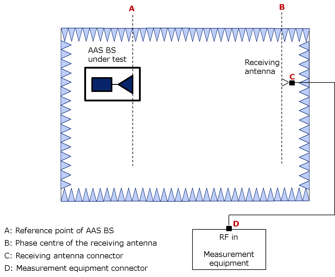
Figure 1: Test setup for EIRP with Anechoic chamber.
Effective Isotropic Sensitivity (EIS)
The test for EIS is similar to the test for EIRP except the BS receiver is under test with a transmitting antenna. The calibration similarly takes into account path loss and cable loss in order to more effectively measure the sensitivity of the receiver. After calibration, the receiving antenna is rotated such that it is aligned with the beam peak direction of the reference antenna that was used during calibration, this ensures that path loss parameters are the same. The signal generator is then set at the minimum EIS level with all the losses accounted for and the throughput is then measured.
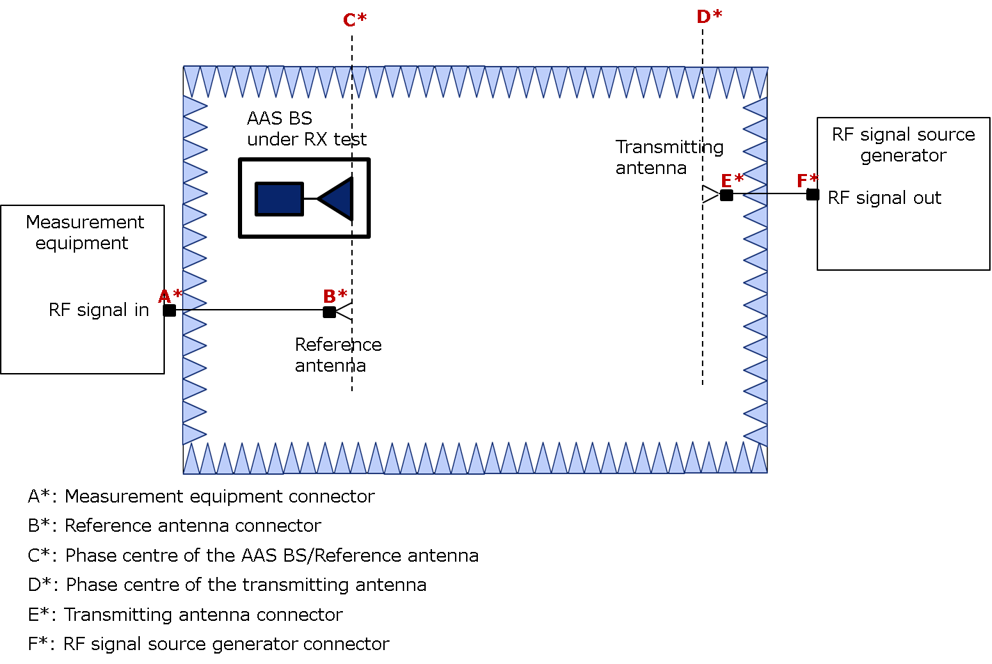
Figure 2: Test setup for EIS with anechoic chamber.
User Equipment Tests
Traditionally, a DUT could be tested with wired connection to the test equipment while only antenna characterizations were necessarily over-the-air (OTA). Newer technologies require that there are new RF cable connections to the DUT and measurements of radiated performance, and antenna reception is performed OTA in order to better understand their true operating conditions. This also includes the ability to control the amount of interference the DUT receives while measuring throughput.
Signal-to-Interference Ratio (SIR)
Normally, throughput is measured as a function of signal power incident to the DUT antennas. This, however, does not provide a realistic assessment of UE performance as UE will often encounter interference (e.g.: inter-cell) that is likely above its noise floor. So, contrary to the testing of BS equipment, UE does require the ability to control what is known as the Signal-to-Interference Ratio (SIR) where an external Additive White Gaussian Noise (AWGN) interferer signal is applied. The SIR can be adjusted any number of ways using either an anechoic chamber or a reverberation chamber. Reverberation chambers allow for vendors to perform antenna characterizations for larger devices (<42 cm) and generally allow for more flexibility than the traditional anechoic chamber where the AUT is fixed in a very exact position.
Figure 3 shows a sample test setup for controlling the SIR in an anechoic chamber. The specification assumes that the interfering signal injected is omnidirectional (isotropic) and uncorrelated to the faded desired signal. The control of SIR is generally accomplished by leveraging a channel emulator or signal generator with the proper settings for the cellular (LTE) signal and interfering signal as well as a dipole antenna (for sensing) in tandem with a spectrum analyzer. The target SIR can be achieved by adjusting gains for the LTE signal and injected interfering signal.
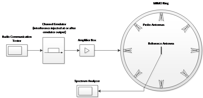
Figure 3: Multi-cluster MIMO OTA test setup for controlling SIR level in anechoic chamber.
Downlink Throughput
The throughput for a MIMO system is the number of correctly received transport blocks in a communication system where a transport block is the basic data unit exchanged between the first layer and the media access control (MAC) layer. The throughput can be measured by essentially replacing the reference antenna in Figure 3 with the DUT. As shown in Figure 4, a software-implemented system simulator (SS) would then create a MIMO signal while an RF channel emulator can recreate the proper fade, scale, delay parameters that are distributed to the test probes (minimum of eight linearly polarized antennas) within the chamber.
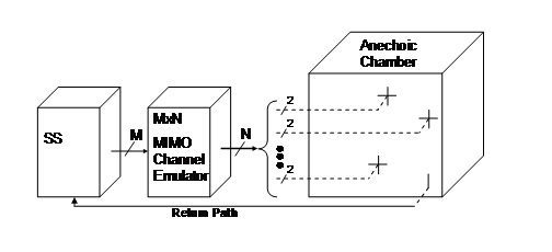
Figure 4: OTA test setup for downlink throughput.
It should be noted that there is another candidate solutions for measuring UE throughput in MIMO systems known as the radiated two-stage (RTS) test methodology where newly defined parameters such as Reference Signal Antenna Power (RSAP) and Reference Relative Antenna Phase (RSARP) are measured. This is accomplished by measuring the full 3D far zone pattern in an anechoic chamber equipped with a positioner. The antenna patterns are then applied to the channel model and coupled into the DUT with a radiated or cabled connection.
Conclusion
Next-generation cellular technologies will likely continually implement MIMO signals with antenna arrays. This, in turn, creates a relatively complex test environment where traditional test methods and characterizations may not adequately present device performance. It has therefore become increasingly

