Robert Brennan, RF Applications Engineer, Analog Devices
A Phase Locked Loop (PLL) and Voltage Controlled Oscillator (VCO) outputs an RF signal at a certain frequency, and ideally, this signal would be the only signal present at the output. In reality, there are unwanted spurious signals and phase noise at the output. This article discusses the simulation and elimination of one of the more troublesome spurious signals—integer boundary spurs.
PLL and VCO combinations (PLLVCOs) which are only capable of operating at integer multiplies of the phase frequency detector reference frequency are known as integer-N PLLs. PLLVCOs capable of much finer frequency steps are known as fractional-N PLLs. Fractional-N PLLVCOs offer much more flexibility and are more widely used. Fractional-N PLLs achieve this feat by modulating the feedback path in the PLL at the reference rate.
While capable of much finer frequency steps than the phase detector reference frequency, fractional-N PLLVCOs have spurious outputs called integer boundary spurs (IBS). Integer boundary spurs occur at integer (1, 2, 3…20, 21…) multiples of the PLL’s Phase Frequency Detector’s reference (or comparison) frequency (fPFD). For example, if fPFD = 100 MHz, there will be integer boundary spurs at 100 MHz, 200 MHz, 300 MHz…2000 MHz, 2100 MHz…
In a system where the desired VCO output signal is 2001 MHz, then there will be an IBS at 2000 MHz—this will appear at a 1 MHz offset from the desired signal. Due to effective sampling in the PLL system, this 1 MHz offset IBS is aliased to both sides of the desired signal. Therefore, when the desired output is 2001 MHz, spurious signals will be present at 2000 MHz and 2002 MHz.
Integer boundary spurs are undesirable for two main reasons:
- If they are at low frequency offsets from the carrier (the desired signal), then the IBS power contributes to integrated phase noise.
- If they are at large frequency offsets from the carrier, then the IBS will modulate/demodulate adjacent channels to the desired channel and result in distortion in system.
In some systems, high integer boundary spurs render some output channels unusable. If a system has 1000 channels in a certain spectrum bandwidth, and 10 percent of the channels have spurious signals above a certain power level, those 100 channels may be unusable. In protocols where spectrum bandwidth costs a lot of money, it is wasteful if 10 percent of the available channels cannot be used.
Integer boundary spurs are strongest when the integer boundary falls within the PLL loop bandwidth from the desired output frequency. That is, if the output frequency is 2000.01 MHz and the loop bandwidth is 50 kHz, the IBS will be strongest. As the output frequency moves away from the integer boundary, the power of the IBS reduces in a calculable and repeatable manner.
Figure 1 shows the worst case integer boundary spur power at each output frequency from 1900 MHz to 2150 MHz (1 MHz steps). It can be seen that, at 2001 MHz, the worst case IBS power is -70 dBc (70 dB below the carrier power). At 2000 MHz, there is no IBS, because the output frequency falls on an integer boundary. The IBS power reduces as the carrier moves away from the integer boundary until the carrier starts getting close to the next integer boundary.
The spurious signals seen half way between the integer boundaries (2049 MHz and 2051 MHz in Figure 1) are second order integer boundary spurs. Second order integer boundary spurs occur half way between integer boundaries. Typically, second order IBS are 10 – 20 dB lower than first order. The ADIsimFrequencyPlanner uses this predictable behavior to accurately simulate integer boundary spur power (and much more).
ADIsimFrequencyPlanner simulates 1st, 2nd, 3rd, 4th, and 5th order integer boundary spurs.
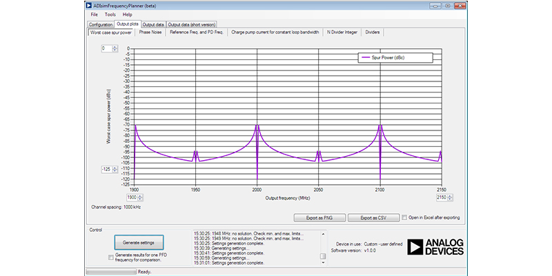
Figure 1: Worst case integer boundary spur power at each output frequency from 1900 MHz to 2150 MHz (1 MHz steps; 100 kHz loop bandwidth; HMC830)
Suppose a certain modulation scheme states that channels with integer boundary spur power above -80 dBc are unusable, then about 10 percent of the channels in Figure 1 are no longer available. To overcome this problem, ADIsimFrequencyPlanner can optimize the PLLVCO configuration to reduce, and in most cases eliminate, integer boundary spurs. Recall that the integer boundary spurs occur at integer multiples of the PFD frequency, and that they are strongest when near the carrier frequency. If the PFD frequency can be changed so that the integer multiple of the PFD frequency falls at a large enough offset from the carrier frequency, then the IBS power will be reduced to a non-problematic level.
This is what the algorithm in ADIsimFrequencyPlanner does—while taking into account the relative powers of the 1st—5th order integer boundary spurs, ADIsimFrequencyPlanner finds the optimum solution that results in the lowest possible integer boundary spurs at the VCO output.
How can the PFD frequency be changed? Traditionally, in a PLLVCO system, the PFD frequency is kept fixed. However, by making the most of a programmable clock distribution source, the PLL reference input divider, and the PLL fractional-N modulator architecture, it is now easy to change the PFD frequency for each output channel.
In the recommended solution, the new HMC7044 clock generation and distribution chip is used. The HMC7044 has 14 ultra low noise outputs; each of the 14 outputs has a programmable divider. By connecting one of these outputs to the PLL reference input, and then programming the output divider as needed, an array of reference frequencies becomes available to the PLL.
The HMC7044 is a clock distribution system applicable to applications that use numerous synchronized clocks for ADCs, DACs, and other system components. Simpler applications that don’t require as many outputs can use a simpler alternative, such as the HMC832 or ADF4351—both are integrated PLL and VCO chips.
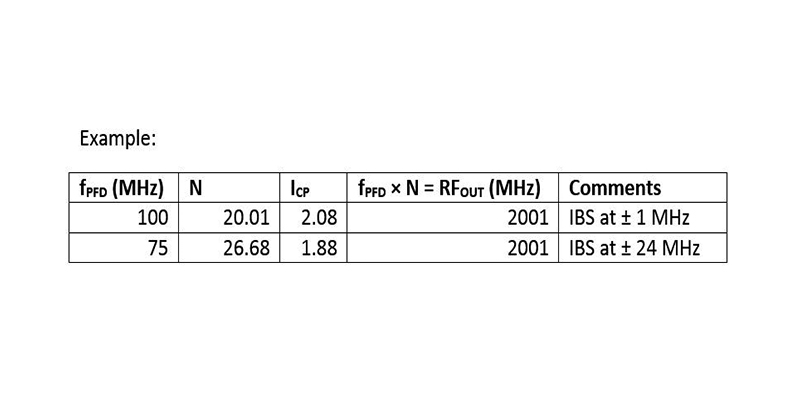
Then, at the PLL reference input, the reference input divider (R divider) can be programmed as needed to divide the array of available reference frequencies to a larger array of PFD frequencies (the PFD frequency is the frequency at the output of the R divider). Thanks to the high-order fractional-N modulator in the PLL, a change to the PFD frequency does not cause a problem in achieving the desired output frequency. Also, the programmable charge pump current of the PLL can be used to compensate for any change in the PFD frequency and therefore maintain a constant loop bandwidth.
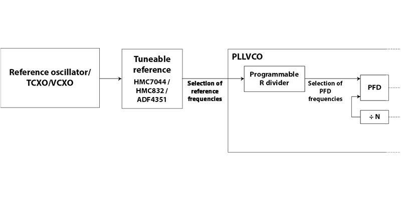
Figure 2: Block diagram showing selection of PFD frequencies.
Where:
ICP = programmable charge pump current
fPFD = PLL PFD frequency;
N = PLL fractional-N value;
RFOUT = VCO output frequency/carrier frequency/desired signal;
The programmable charge pump current changes inversely with the PFD frequency—as PFD frequency increases, the charge pump current must decrease. This serves to keep the loop filter dynamic constant.
When using ADIsimFrequencyPlanner, the user inputs the required output frequency range, step size, PFD frequency and reference frequency constraints, and loop filter parameters. The user also selects the available clock generator output dividers and PLL reference input dividers. ADIsimFrequencyPlanner then steps through each desired frequency step, and calculates the optimum PFD frequency from the array of available PFD frequencies. ADIsimFrequencyPlanner then returns the required divider settings and charge pump current to the user. The data can be easily exported to a lookup table that the end application’s firmware can read and then program the HMC7044 and the PLLVCO accordingly. ADIsimFrequencyPlanner also generates a series of plots to show the user what is happening.
In Figure 3, the user has used the same configuration as Figure 1, except this time, the PFD frequency can is optimized by changing the HMC7044 output divider and the PLL reference input divider. The un-optimized simulation is also shown in gray for comparison.
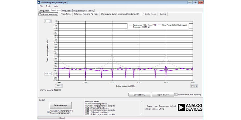
Figure 3: Same output configuration as Figure 1 but now, the PFD frequency is optimized.
It can be seen in Figure 3 that across the output range (19002150 MHz in 1 MHz steps), all integer boundary spurs are now <-95 dBc. This represents a dramatic improvement and makes a very high percentage of the desired outputs all the same excellent quality.
Applying ADIsimFrequencyPlanner to a Wideband VCO
In an experiment to measure the accuracy and effectiveness of ADIsimFrequencyPlanner, several high performance parts were put together and evaluated in the laboratory. In the experiment, the following parts were used:
- HMC7044 clock generation and distribution:
- Up to 3.2 GHz output,
- JESD204B compatible,
- Ultra low noise (<50 fs jitter, 12 kHz – 20 MHz),
- -142 dBc/Hz at 800 kHz offset from 983.04 MHz output, and
- 16 programmable outputs.
- ADF5355 integrated PLL and VCO:
- 55 MHz to 13.6 GHz output,
- 5 mm × 5 mm LFCSP package, and
- -138 dBc/Hz at 1 MHz offset from a 3.4 GHz output.
- HMC704 ultra low noise PLL:
- RF input up to 8 GHz,
- 100 MHz maximum PFD frequency, and
- -233 dBc/Hz normalized phase noise floor.
Although the ADF5355 has an internal PLL, the HMC704 was used to externally lock the ADF5355 VCO. There are two main benefits to this technique:
-
The overall phase noise benefits from the industry leading VCO phase noise of the ADF5355 and from the industry leading PLL phase noise of the HMC704.
-
Isolating the VCO and PLL results in less unwanted signal coupling and therefore reduces the power of spurious signals.
ADIsimFrequencyPlanner was used to optimize an output range from 4800 MHz to 6300 MHz in 250 kHz steps (6000 steps). At each step, the optimum divider settings (therefore optimum PFD frequency) and charge pump current was programmed to the HMC7044, ADF5355, and HMC704.
Once the parts were programmed to an output step, a spectrum analyzer measured the carrier power and power of the 1st and 2nd order integer boundary spurs. The spectrum analyzer used a very narrow frequency span and resolution bandwidth—even so, at most channels only noise was measured because the integer boundary spur power was lower than the instrument noise floor.
The following measurement was taken with the PFD frequency constrained between 60 MHz and 100 MHz. The loop bandwidth and phase margin were 17 kHz and 49.6°, respectively.
Figure 4 shows the measured and simulated results for the HMC7044, ADF5355, and HMC704 solution.
-
6000 output channels were simulated and measured.
-
Most integer boundary spurs are simulated around -120 dBc. This is below the noise floor of the spectrum analyzer so only noise was measured.
-
Most frequencies have spurs below -100 dBc! A typical requirement is -70 to -80 dBc.
-
The only region where the optimization doesn’t improve the IBS is less than 2 MHz wide and occurs at 2 × HMC7044 master clock—at this frequency, no combination of dividers can improve the IBS performance. Alternative solutions are offered below.
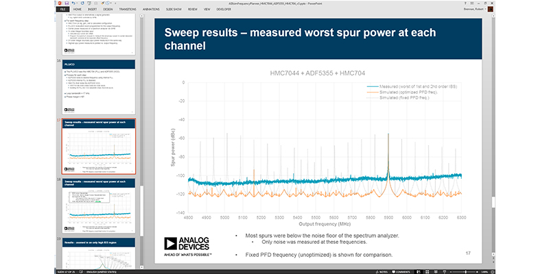
Figure 4: Measured and simulated results for the HMC7044, ADF5355, and HMC704. Note the narrow frequency range where optimization was not possible is correctly simulated by ADIsimFrequencyPlanner. At most other frequencies, the measurement was limited by the noise floor of the spectrum analyzer.
There is only one very narrow range of frequencies where optimizing the PFD frequency does not improve the IBS performance. This frequency range is twice the system master clock (in this case, 2949.12 MHz × 2 = 5898.24 MHz).
At this frequency, if the application is capable, it is recommended to shift the carrier frequency to a nearby, cleaner frequency and then, shift the baseband frequency in digital (NCO) to compensate. For example, offset the carrier frequency 2 MHz and offset the digital baseband frequency 2 MHz to compensate. Alternatively, if possible in the system, change the master clock frequency to create a clean output frequency.
If the simpler solution mentioned above (using the HMC832 or ADF4351 instead of the HMC7044), then no problem frequencies exist!
From Figure 3, it can be seen that ADIsimFrequencyPlanner:
- simulates integer boundary spurs accurately,
- successfully optimizes the reference source and PLLVCO system for excellent integer boundary spur performance. This makes more channels in a range usable and therefore increases value for money in expensive frequency spectrums, and
- simulates wide frequency range systems very quickly. Manually the process can take days or even weeks. The above 6000 step simulation takes less than one minute in ADIsimFrequencyPlanner.

