Learn how to use patch antennas and phase shifting to create a phased-array antenna to steer RF signals.
Phased-array antennas have been used in a variety of applications for decades. Recently, they have become more important in mobile wireless as the frequencies have increased, allowing for smaller antenna arrays. 5G systems operating in the Frequency Range 2 (FR2) band (24.25 GHz to 52.6 GHz) make good use of these steerable antennas.
Patch Antenna
A common building block for a phased array antenna is the patch antenna. This antenna is made up of a flat rectangular conductor (the patch) mounted over a larger flat conductor, often referred to as the ground plane (Figure 1). As shown, the patch is square but other shapes can be employed. A dielectric material separates the patch from the ground plane. The feedline is shown simplistically as a conductor entering from the left, but you can choose the exact connection point and method to optimize the impedance match.
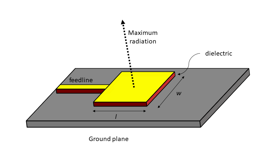
Figure 1. The patch antenna is made up of a rectangular conductor on top of a ground plane, separated by a dielectric material.
A square patch antenna has l = w =~ λ/2 or half wavelength. Fringing effects at the edges of the patch will cause it to act electrically larger, so the patch will be somewhat smaller than a half wavelength. Also, the dielectric material between the patch and ground can affect the resonant frequency, also requiring the antenna dimensions to be smaller. A variety of construction techniques can be used to implement a patch antenna, including sheet metal (for larger antennas) or microstrip (PC board) and monolithic microwave integrated circuits (MMICs) for small geometries.
Maximum radiation from the antenna is perpendicular to the patch, away from the ground plane. A typical patch antenna has a gain of approximately 8 dBi to 9 dBi and a –3 dB beam width of about 65 degrees [Ref. 1]. (The term dBi indicates the gain of the antenna relative to an isotropic radiator, a mythical antenna that radiates equally in all directions. It is often used as the standard of comparison when discussing antenna performance.)
Size matters
The general trend of increasing frequency in wireless systems has caused the patch antenna to become much more common. Let us consider the frequency of 150 MHz in the VHF range.
In free space, a half wavelength is given by:
λ/2 = 150/f
where λ is in meters and f in MHz
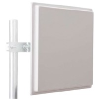
For a 150 MHz antenna, the patch antenna is about 1 m on each side. That’s far too large to integrate into a modern smartphone or tablet. At frequencies near 1 GHz, the patch antenna becomes more manageable, with a half wavelength of 15 cm. Figure 2 shows a common 900 MHz patch antenna.
In the 5G FR2 band the physical dimensions are even smaller. At 28 GHz, a half wavelength is ~5 mm. As mentioned earlier, the dielectric material used between the patch and ground plane can shrink the half wavelength considerably, perhaps 30% or more.
Linear Antenna Array
With smaller antenna geometry, we can combine multiples of them into an array to increase the antenna gain. We could just feed all the patch antennas in phase and produce higher gain than an individual patch. We can, however, control the phase of each individual signal going to each patch to create an electronically steerable antenna.
Figure 3 shows a linear array of eight antennas driven by a single transmitter. The signal to each antenna element is controlled by its own individual phase shifter, which delays the signal in time. Starting at the bottom element, which has the smallest phase shift, each element above it has progressively more phase shift applied. As each element radiates, a combined wave front is formed with the bottom of the wave further out in front. The higher antenna elements also radiate the signal, but with an additional delay. Done correctly, this creates a radiated wave that proceeds at an angle θ relative to a line that is perpendicular to the antenna array. Increasing amounts of phase shift increases θ such that the antenna pattern can be steered in the desired direction.
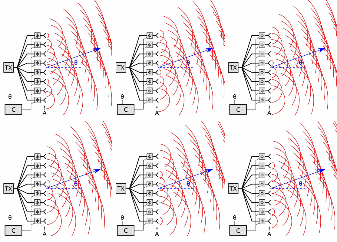
Figure 3. Controlling the phase of the signal provided to each patch antenna in a linear array creates a steerable antenna. Source: Wikipedia.
The antenna system in Figure 3 shows control of the phase only. In the general case, each antenna element could also have individual amplitude control. This provides flexible control over the radiation pattern of the antenna, commonly called beamforming.
Phased Array Antenna
The linear array concept can be extended to two dimensions by using a matrix of patch antennas, as shown in Figure 4. The example shown is an 8 x 8 array of antenna elements, resulting in 64 total elements. The feedlines are not shown in the figure for simplicity, but each antenna can be driven individually.

Figure 4. An array of 64 patch antennas (8×8) combine to create a phased-array antenna. (Feedlines not shown.)
In a previous article, More antennas, faster data transfer, we discussed how beamforming can be used to optimize data rates to multiple users (Figure 5). The overall effectiveness of a wireless system may be improved by concentrating the signal to multiple mobile devices while simultaneously nulling out interfering signals that may be present. This requires advanced control of the radiation pattern, made possible with phased-array antennas.
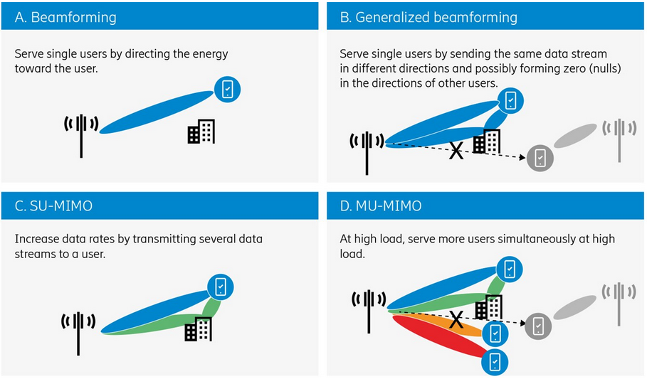
Figure 5. Phased-array antennas can direct multiple beams to wireless devices, optimizing overall system performance. Graphic courtesy of Ericsson.
Figure 6 shows an implementation of a 64-element array for 28 GHz. The outer rows of patches were not used, just the inner 8 x 8 antenna array, which is roughly 50 mm (two inches) across. This is a good example a compact antenna that contains many elements.
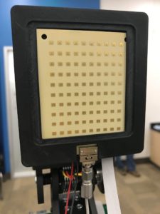
Figure 6. This compact 64-element phased-array antenna for 28 GHz was developed at UCSD. Photo: Keysight Technologies.
While this article provides a basic understanding of phased array antennas, the practical reality of implementing such an antenna involves many design decisions such as materials used, mechanical dimensions, spacing of the elements and both analog and digital techniques for controlling the individual signals. To dive deeper into those issues, review the references below, which will provide the next level of insight.
References
1. “The Fundamentals of Patch Antenna Design and Performance,” Gary Breed, High Frequency Electronics, March 2009, https://www.highfrequencyelectronics.com/Mar09/HFE0309_Tutorial.pdf
2. “The Basics of Patch Antennas, Updated,” D. Orban and G.J.K. Moernaut, Orban Microwave Products, Sept 2009, http://orbanmicrowave.com/wp-content/uploads/2014/12/Orban-Patch-Antennas-2009-rev.pdf
3. “Phased Array Antenna Patterns—Part 1: Linear Array Beam Characteristics
and Array Factor,” Peter Delos, Bob Broughton, and Jon Kraft, Analog Dialogue, Vol 54 No 2, May 2020, https://www.analog.com/media/en/analog-dialogue/volume-54/number-2/phased-array-antenna-patterns-part-1-linear-array-beam-characteristics-and-array-factor.pdf


Bob,
This is great. It’s a great explanation of phased array antennas and beam steering. I love your writing style because it’s straightforward and accurate and explains why a physical phenomenon is useful.