At OFC 2022, OIF demonstrated products from several companies communicating with each other based on a standard for interoperable coherent optics. Other demonstrations included a 112 Gb/sec electrical link, flexible Ethernet, co-packaging, and a 224 Gb/sec technology proposal.
Because the demand for more data and faster data rates never ceases, optical network links must evolve to deliver the data. 400 Gb/sec links are common within and between data centers, with 800 Gb/sec products in development and 1200 and 1600 Gb/sec links in discussion. The 2022 OFC Conference saw several industry demonstrations on the latest in optical transport technology, courtesy of the Optical Internetworking Forum. The organization demonstrated the results of several standards efforts.
Interoperable coherent optics
Coherent optics is one of the techniques to boost data rates. It modulates amplitude, frequency, and polarization as explained in How coherent optics increase data rates.

Nathan Tracy
Unfortunately, coherent optical modules have suffered from a lack of interoperability. That’s according to Optical Internetworking Forum (OIF) director of marketing Nathan Tracy of TE Connectivity. “you needed to use optics from the same company at both ends of the link,” Tracy told EE World following the conference. Describing a “secret sauce in the DSP, Tracy said “There are differences in modulation and coding. There’s a need for low-cost interoperable optical links that connect data centers.”
Tracy explained that the needed reach for low-cost interoperable links is 120 km, long enough to connect most data centers. Because of that distance, the industry could make some concessions in performance not possible in longer reaches. OIF demonstrated the 400ZR project using silicon, optical modules, routers, and switches from Cisco, NeoPhotonics, Ciena, Fujitsu, Juniper, and Marvel.
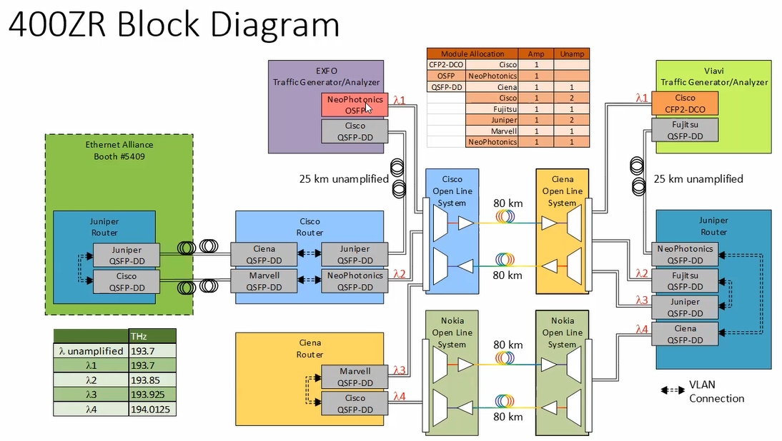
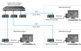
Figure 1. OIF demonstrated a network using interoperable coherent optics.
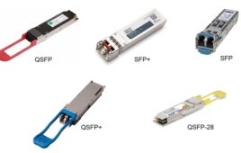
“OIF’s goal was to write an interoperability spec and this demonstration proved it,” said Tracy. The demo used optical modules in several form factors such as QSFP, CFP-2 and QSFP-DD. OIF is now developing an interoperability spec for 800G coherent optics.
Figure 1 shows a schematic of the interoperability demonstration network. In the video, Tracy walks you through the demonstration’s equipment and data paths.
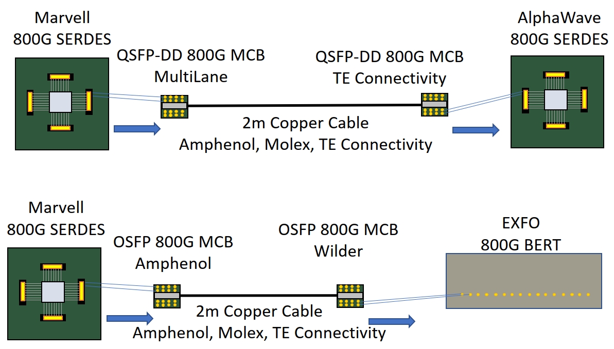
Figure 2. OIF demonstrated a long reach 112 Gb/sec electrical interface.
112G electrical interface
Because all optical modules need electrical interfaces, OIF demonstrated 112 Gb/sec electrical interfaces that cover several reaches. In this demonstration, companies contributed silicon, test boards, cable, connectors, and test equipment. Figure 2 shows a diagram of the 112G-MR — medium reach, 2 m copper cable — demonstration. The links consist of eight 112 Gb/sec lanes, making it an 800 Gb/sec link. The actual data rate per lane was 106.25 Gb/sec using a PRBS31Q pattern with PAM4 modulation.

Figure 3. Flexible Ethernet adds protocols to set a data rate as needed.
IEEE defines Ethernet in its 802.3 series of specifications, which include specifying of data rates. Suppose a physical infrastructure can’t support a full data rate specified in the standards, but can support more than the next lower rate? For example, a network that can support 35 Gb/sec but not 40 Gb/sec? In that case, it would drop to perhaps 25 Gb/sec. That results in underutilized capacity. Flexible Ethernet (FlexE) lets a network run at the highest data rate it can support. According to Tracy, FlexE lets an operator best allocate resources as needed when using network slicing.
OIF has published a white paper that describes FlexE. Figure 3 shows a typical FlexE protocol stack.
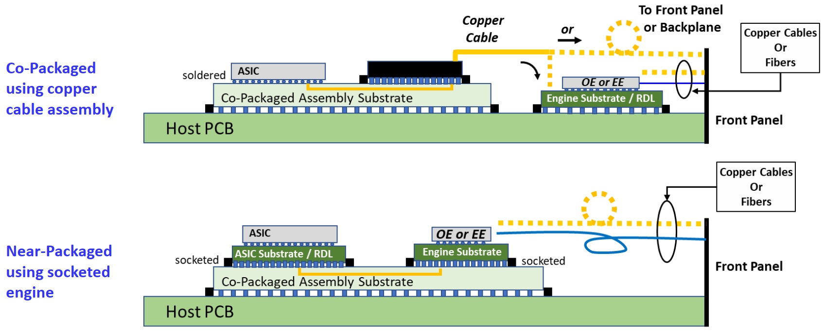
Figure 4. Co-packaging move the optics next to or within switch silicon to improve signal integrity.
Co-packaging
“Co-packaging has become a huge buzz in the industry,” said Tracy in describing the demo. “We’re relocating the transceiver function to move it closer to the network switch silicon” (Figure 4). Traditionally, electrical-to-optical connections occur at the edge of a network line card. At today’s data rates, the PCB traces are simply too long to avoid losses and skewing in the signals, requiring considerable processing power to equalize the signals for transmission. Moving the optics shortens the distance and reduces signal-integrity problems. “Co-packaging places the optics inside a switch, said Tracy. “That reduces the amount of power needed for equalization.”

Cathy Liu
224G: The next electrical interface
While 800 Gb/sec optical links are in development, there’s already research underway for 1.2 Tb/sec and 1.6 Tb/sec links with test equipment already available. At 112 Gb/sec per lane, that’s too many lanes needed to support these speeds. Early 800 Gb/sec links will operate using 8 × 112 Gb/sec lanes, doubling the data rate and using half as many lanes improves efficiency and cuts the number of PCB traces in half. That’s where the next specification covering 224 Gb/sec electrical lanes make sense. In February 2022, OIF published a white paper, Next Generation CEI-224G Framework.
OIF president Cathy Liu of Broadcom discussed four 224 Gb/sec projects currently underway. The projects cover these electrical interfaces:
- Extra-short reach (XSR), on-package;
- Very-short reach (VSR), chip-to-optical module;
- Medium reach (MR), chip-to-chip;
- Long reach (LR), backplane and copper cable.
There are still applications for the long-reach backplane and copper cable electrical interfaces, according to Liu. “We’re looking into the possibility of achieving 224 Gb/sec links over those long reaches.” The project teams need to establish parameters such as modulation, baud rate, and bit-error rate (BER) to achieve the data rate. Those decisions will be based on characterizing signal losses due to insertion loss and other signal degradations. For modulation, the most likely choice will be PAM4 but there’s still work to do in terms of receiver tests.
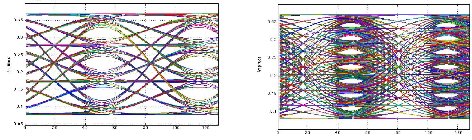
Figure 5. A PAM4 signal (l) has four amplitude levels, each representing two bits. A PAM8 signal has eight levels, each representing three bits. Source: IEEE
Each time a data rate increases, a new challenge takes hold. Those challenges often come from the physics of PCBs, electromagnetic issues, or some other obstacles that previously weren’t factors at lower speeds. “We need to double the PAM4 baud rate to 112 Gbaud,” said Liu. That impacts every aspect of the transmission channel, including IC packages, PCB traces, connectors, optical module design, and so on. Issues such as reflections, return loss, and crosstalk must be overcome. In addition, the SerDes will need to cope with doubling the baud rate. That affects its DSP and ADC architecture. Of course, cost and power are always issues.
If the channels can’t support the bandwidth needed for 112 Gbaud PAM4, then higher-order modulations such as PAM6 or PAM8 must be considered. That means more and smaller voltage levels and smaller signal eyes, which bring their own set of problems. Figure 5 compares PAM4 and PAM8 signaling. The smaller differences between voltage levels put more strain on receivers, making distinguishing between bit combinations more difficult. Doubling the PAM4 baud rate is preferred, just as it was with non-return-to zero (NRZ) before PAM4 was finally adopted.
What’s the 224 Gb/sec timeline? According to Liu, OIF plans to have a draft specification ready in 2023 with a published specification ready in 2024 or 2025.

Tell Us What You Think!