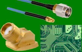
The days of specialty military connectors are numbered so the cable and connector industry is reinventing this interface. By Ernest Worthman
It’s no secret that there is tremendous pressure for the military to go with COTS components whenever possible. Interconnect is one area where that pressure is hot and heavy, since connectors are relatively uncomplicated devices, when compared to some of the other cutting edge componentsFor military and aerospace applications, connector designers’ biggest design issue is high-speed and high-density. These two particular requirements tax the cost restrictions mantra, as well as commercial standards, heavily. They also challenge connector design in the sense that connectors must meet these HS/HD requirements, as well as other significant parameters, within HS/HD. Some of them are: Extended/extreme temperatures; ESD resistance/immunity; ultra-miniature footprint (0.025 inches pitch and less); hermetic sealing; controlled impedance contacts; short electrical travel paths and ruggedized construction.
The Digital Dilemma
As more and more circuits and components make move to digital, from analog, an new paradigm arises as well. First of all, the physical size of digital components and circuits are generally smaller than analog. This puts pressure on the connectors to follow suite. But the lighter and smaller footprint still has the same metric requirements and issues as its bigger and badder brother.
For example, creating 0.025 inches pitch connectors that can meet the MIL-C-83513 specification usually demands a design incorporating a metal housing. but the dimensions are much tighter so typical pin and socket system that can handle the shock and vibration and mates/de-mates generally don’t work. The first line of though is to find a metal that can meet both the size and ruggedness requirement. Typically, different metals are examined for applicability. And, one solution that has evolved is the solid gold-plated receptacle bores of beryllium-copper (BeCu). Given sufficient demand, this design could easily become commercial.
Let’s Talk Static
Another critical issue in mil specs is ESD. Given modern day weapons development in areas such as EMP disruptors and e-bombs, ESD is a critical parameter.
EMI shielding has become increasingly important in a variety of military and aerospace applications as demands for high-speed digital circuits that move data at megabit speeds have increased — a virtual playground for electrical noise and interference. As miniaturization becomes the standard, circuits become more and more crowded and integrated, making EMI/ESD shielding even more of a critical element.
Solutions to this include, for example, a shield on the cable that can be sealed to the connector to maintain integrity of the signal path. Such a design is typically a stainless steel braided shielding, encasing the cable and sealed as it enters the back of the connector. This method effectively isolates adjoining circuits.
The Connector is Now Component
The trend for the military is to stop viewing connectors as individual components and see them as part of the system. What seems to be happening is instead of having a plug-in module, the government is thinking of a whole board as an element. This has some interesting ramifications. For example, a connector may be integrated onto a circuit board, where at one time it may have been a stand-alone.
In such a case, the whole board is subject to a particular mil-spec, which may or may not have the same requirements as the connector spec. The commercial connectors may be built to less than mil-spec for vibration. However, the enclosure can be designed with dampening that can offset the difference between what the connectors are tested to and what the enclosures will be subjected to.
Emerging Designs
Increasing military and aerospace demands for higher speed applications, noise suppression, and the adoption of FibreChannel protocols has created a new breed of standard products.
Solutions include OEMs developing quadaxial contacts and putting high-speed copper into a Size 8 contact. Such designs have demonstrated the ability to control emitted noise by keeping the groupings of the quad cable construction symmetrical.
On the fiber optic front, expanded beam fiber optic interconnection technology offers high reliability in extreme vibration and thermal environments. The fibers are sealed behind a glass lens, providing dust, moisture, mud, and other contaminant protection. While expanded-beam connectors have not seen widespread use, mainly due to cost and lower performance, recent advances in precision machining, metrology and connector design have brought them more into line with conventional connectors in price and performance.
Trends in Technology
The newest demand is for leading-edge technologies is the nanoconnector.
Currently, most boards cannot support connector technology smaller than 25 mils — the PCB process hasn’t caught up with the density. One solution is to make future boards with surface-mount nanoconnectors that interface directly on the PC boards. This eliminates one level of wiring.
Design problems exist for military and aerospace connectors that don’t exist in typical commercial applications. The design challenge is to find a way to get the lower-voltage circuitry in the military version to go with the reduced pitch parameters and still remain viably reliable. Some of the military power levels are still high enough to burn up micro-pitch connectors.
Finally, something that has been successful in high-speed SCSI interfaces — LVDS. This approach offers a stable impedance differential signal, compatible with high-speed signaling schemes such as LVDS. It uses differential signaling to control the impedance at the connector. This is particularly popular with military avionics because it so reliable at high data rates, and makes it easy to manage impedance. Glossary of Acronyms
COTS – Commercial Off The Shelf
EMP – Electromagnetic Pulse
ESD – Electrostatic Discharge
HS/HD – High-Speed/High Density
LVDS – Low-Voltage Differential Signaling
PCB – Printed Circuit Board
SCSI – Small Computer System Interface