Antennas come in abroad range of sizes, styles, and configurations to meet frequency, bandwidth, directivity, and many other objectives; the PIGA and Yagi antennas are rather different yet widely used versions.

Fig 1: The half-wave dipole and the quarter-wave monopole antennas are the building blocks which are the basis for nearly all advanced antenna configurations. (Image: EnOcean)
With a few highly specialized exceptions, all antennas in general use—ranging from tiny ones in wearables to huge broadcast-transmitter designs — are extensions, enhancements, and modifications of two basic types. These are the balanced half-wavelength dipole (also called a Hertz antenna) without ground reference, and the electrically unbalanced quarter-wavelength monopole (Marconi antenna) positioned at right angles to a ground plane (Figure 1). [Note: The term “aerial” is used in the United Kingdom and other regions of the world for “antenna” but we will stay with the US-English terminology.]
It’s important to note that there is no such thing as a general “optimum” antenna even within a given configuration, because the needs and priorities of each antenna application differ. Certainly, for most circuit and systems designs, you naturally want to minimize size, weight, and power (SWaP), and cost while maximizing other factors such as speed/performance and reliability. That all makes sense and is logical to the extent it can be accomplished with the right tradeoffs.
It’s different for antennas. Even within a defined general configuration, what’s “best” depends on the unique demands of the situation. Some applications need a wider bandwidth to capture or transmit signals across a wide spectrum; others must have a narrow bandwidth to minimize noise.
Perhaps the design calls for a very narrow antenna beam width to focus primarily on a targeted receiver (for transmitters) or transmitter (when receiving) while another design for the same center frequency needs a wider bandwidth to reach out broadly. There’s a place and need for each set of performance attributes even if the basic antenna designs are similar. In short, no single antenna type or configuration serves all the needed bands and roles in modern systems, with a large commercial aircraft as an illustrative case (Figure 2).

Figure 2. Modern aircraft require a large number and wide range of antenna types to meet the diverse functions and bands these antennas must support. (Image: Boeing via SWLing Post)
By using the two basic antenna types of Hertz dipole and Marconi monopole as starting points, engineers have devised countless variations tailored to the needs and priorities of the application. The complexity is such that there is no single, definitive way to categorize the genealogy of antennas, as their relationships depend to a large extent on the perspective of whoever is drawing that family tree.

Figure 3. This antenna “family tree” is just one way of categorizing the genealogy of antenna principles and configurations. (Image: Fayllar.org)
In other words, a diagram made with respect to electromagnetic field principles used in a slotted antenna is different than the one that is instead focused on the actual construction via a microstrip antenna but using that principle. The family tree shown in Figure 3 is one good representation.
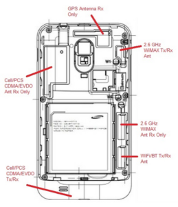
It’s not just systems such as large aircraft that need multiband capabilities, which cannot be met with a single external or internal antenna. Even a somewhat dated smartphone such as the Samsung Galaxy (circa 2011) had to support different frequencies and modes via six distinct antennas. There’s also a bottom conducting plane (the ground plane) as one large plane that extends throughout the length and breadth of the phone. (Figure 4). Of course, the roll-out of 5G — with frequencies ranging from 600 MHz to mmWave — connectivity is adding to the challenge of multiband support.

Fig 4: The 2011 Samsung Galaxy S embeds six distinct antennas, as follows: 1: 2.6 GHz WiMAX Tx/Rx Antenna; 2: 2.6 GHz WiMAX Antenna Rx Only (as a diversity antenna); 3: WiFi/Bluetooth Tx/Rx Antenna; 4: Cell/PCS CDMA/EVDO Tx/Rx Antenna; 5: Cell/PCS CDMA/EVDO Rx Only (as a diversity antenna); 6: GPS Antenna Rx Only. (Image: RAYmaps)
Many of today’s devices such as smartphones or Internet of Things (IoT) require a tiny antenna that fits completely within the small enclosure and must operate on multiple bands. In other cases, the antenna is “out in the open” and so offers the designer many degrees of design freedom.
This three-part series will look at two very different and widely used antennas: the planar inverted-F antenna or PIFA (not to be confused with the similar acronym PIGA, the pendulous integrating gyroscopic accelerometer) and the Yagi-Uda antenna (often referred to simply as a Yagi antenna).
Part 2 will post on January 18, 2023 with Part 3 posting on January 23.
EE World Related Content
- 5 tips for designing with embedded antennas
- How distributed antenna systems bring cellular indoors
- The microstrip antenna, Part 1: Basics
- The microstrip antenna, Part 2: Implementation
- What materials can be used to make miniature antennas?
- The basics of dielectric resonator antennas
- Practicalities of specifying 5G antennas for the IoT
- How distributed antenna systems bring cellular indoors
- What to consider when selecting a Wi-Fi antenna
External References
PIFA
- EnOcean, Application Note 102, “Antenna Basics – Basic Antenna Design Considerations for EnOcean based Products”
- Raymaps, “Antennas on Samsung Galaxy S”
- Antenna-Theory.com, “Inverted-F Antenna (IFA)”
- Antenna-Theory.com, “PIFA – The Planar Inverted-F Antenna”
- European Union Digital Library, “Multiband Planar Inverted F Antenna (PIFA) for ISM,
WLAN and WiMAX Applications”
Yagi Antennas
- Wikipedia, “Yagi–Uda antenna”
- Electronics Notes, “Yagi Antenna Theory: Yagi Antenna Basics”
- Everything RF, “What is a Yagi Antenna?”
- Yagi, Hidetsu; Uda, Shintaro (February 1926). “Projector of the Sharpest Beam of Electric Waves” (PDF). Proceedings of the Imperial Academy. Imperial Academy. 2 (2): 49–52. doi:2183/pjab1912.2.49. Retrieved 11 September 2014.
- HamUniverse, “Basic Yagi Antenna Design for the Experimenter”
- Luxorion, “From Longwire to Yagi”


Excellent.