Antennas come in a broad range of sizes, styles, and configurations to meet frequency, bandwidth, directivity, and many other objectives; the PIGA and Yagi antenna are two different yet widely used versions.
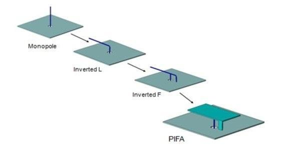
Figure 1. The classic monopole has gone through several evolutionary stages, with the IFA being the third stage, immediately preceding the PIGA. (Image: European Union Digital Library)
Part 1 of this three-part series set the stage by explaining how many of today’s antennas are based on one of two concepts. Part of the solution to the antenna dilemma, whether single or multiple, is to look at configurations that offer new options for designers which are based on monopoles or dipoles but are not constrained by their basic form factor.
One such antenna design is the PIFA. What is a PIFA? Start with the inverted-F antenna (IFA) – proposed in 1958 – which is the third step in the evolution away from the basic monopole antenna and a variant of the patch antenna (Figure 1). (From the side, it looks somewhat like the letter “F,” hence the name.)
In this arrangement, the monopole element runs parallel to a ground plane and grounded at one end, and the antenna has a low impedance on the order of a few ohms (in contrast, the classic base-fed λ/4-wavelength monopole has an impedance of 36.5 Ω.)
The antenna feed is placed at an intermediate point a short distance from the grounded end. By adjusting the placement of the feed and other “tweaks and trims” its impedance can be made to match the power amplifier (PA) feed, so it is an efficient radiator without the need for additional matching components.
The original inverted-F antenna used a bent wire for a monopole. The PIFA modifies the IFA by using a flat element placed immediately above the ground plane with a shorting pin between them. The PIFA is defined by just a few basic dimensions (Figure 2).
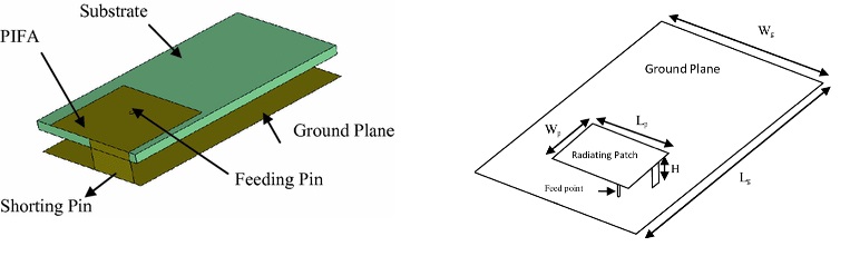
Figure 2. (left) The PIFA is a modified IFA, with a flat element rather than a bent wire above the ground plane; (right) it has just a few critical dimensions. (Image: Springer Nature; European Union Digital Library)
In addition to being resonant at a quarter wavelength and thus so reducing the space needed for the complete antenna function, the PIFA has other desirable antenna properties including a low profile and an omnidirectional pattern. In a first-order analysis, the PIFA’s critical resonant frequency fr is determined by a few basic dimensions and simple equations where λ is the wavelength, εr is the dielectric constant, and c is the speed of light (see equations).

These three relatively simple equations use the dimensions of the PIFA and some physical constants to calculate a first-order analysis of the PIFA’s resonant frequency. (Image: European Union Digital Library)
Of course, a full electromagnetic field analysis must add to these equations to accommodate the effects of fringing, material thicknesses, nearby components, and other real-world considerations.
Off-the-shelf PIFAs ease design-in
PIFAs can be fabricated using microstrip PC-board technology. Using the PC board as the ground plane is, however, challenging in practice, as doing so increases the board size, constrains the layout of the PC board, and reduces the degrees of freedom that the designer can trade off.
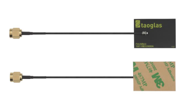
Figure 3. The Taoglas FXUWB20.01.0100C UWB PIFA antenna for 3 GHz -to-10 GHz measures 35 mm × 24.5 mm × 0.2 mm and is targeted at applications using UWB commercial bands 1 through 15. (Image: Taoglas)
Instead, designers often choose to use standard, standalone PIFAs available as complete, drop-in components with defined performance and attributes. These do not require PC-board space for their underlying ground plane and even allow designers to make use of the space above the board.
For example, the Taoglas FXUWB20.01.0100C is a small-form-factor, flexible, ultra-thin PIFA for 3 GHz-to-5 GHz and 6 GHz-to 10-GHz ultra-wideband (UWB) designs (Figure 3). It measures just 35 mm × 24.5 mm × 0.2 mm and attaches by a simple “peel and stick” process to non-metal surfaces via an adhesive. It allows designers to use only one antenna to simultaneously cover the entire available UWB commercial bands 1 through 15.
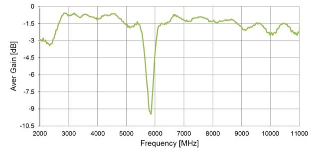
Figure 4. The Taoglas PIFA antenna has a gain notch at 5.8 GHz to attenuate undesired Wi-Fi signals. (Image: Taoglas)
Electrical connection of the antenna to the circuit board is simple due to the integral 100-mm long coaxial cable terminated in a 1.37 mm SMA plug connector. The antenna is deliberately deigned to reject 5.8 GHz Wi-Fi signals within the broad 3 GHz-to-10 GHz span of the commercial UWB channels (Figure 4).
Part 3 (available 23 January 2023) looks at the Yagi-Uda antenna, which is dramatically different than the PIFA.
EE World Related Content
- The microstrip antenna, Part 1: Basics
- The microstrip antenna, Part 2: Implementation
- What materials can be used to make miniature antennas?
- The basics of dielectric resonator antennas
- Practicalities of specifying 5G antennas for the IoT
- How distributed antenna systems bring cellular indoors
- What to consider when selecting a Wi-Fi antenna
- Getting one wire to do more, Part 4 – headphone wire as antenna
- Software tool helps designers place antennas in design
- 5 tips for designing with embedded antennas
- Metamaterials, mmWave antennas, 3D radar and holographic beamforming
External References
PIFA
- EnOcean, Application Note 102, “Antenna Basics – Basic Antenna Design Considerations for EnOcean based Products”
- Raymaps, “Antennas on Samsung Galaxy S“
- Antenna-Theory.com, “Inverted-F Antenna (IFA)
- Antenna-Theory.com, “PIFA – The Planar Inverted-F Antenna”
- European Union Digital Library, “Multiband Planar Inverted F Antenna (PIFA) for ISM,
WLAN and WiMAX Applications”
Yagi Antennas
-
- Wikipedia, “Yagi–Uda antenna”
- Electronics Notes, “Yagi Antenna Theory: Yagi Antenna Basics”
- Everything RF, “What is a Yagi Antenna?”
- Yagi, Hidetsu; Uda, Shintaro (February 1926). “Projector of the Sharpest Beam of Electric Waves” (PDF). Proceedings of the Imperial Academy. Imperial Academy. 2 (2): 49–52. doi:2183/pjab1912.2.49. Retrieved 11 September 2014.
- HamUniverse, “Basic Yagi Antenna Design for the Experimenter”
- Luxorion, “From Longwire to Yagi”


Tell Us What You Think!