Yagi antennas have long been popular as beam antennas for amateur radio. Here’s how they work.
Part 1 of this series introduced two fundamental antenna concepts while part 2 discussed the PIFA antenna. Within the universe of available antennas, there’s one which has been a long-time favorite among do-it-yourself (DIY) enthusiasts as well as for commercial and professional situations: the Yagi antenna (or more correctly, the Yagi-Uda antenna) (Figure 1).
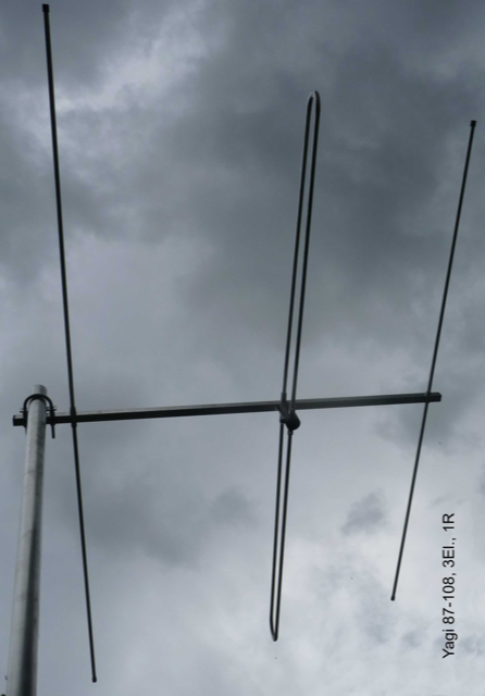
Figure 1. The basic Yagi antenna is a three-element antenna widely used in commercial, residential, and military application, it is often see on rooftops or masts. (Image: EuroCaster/Denmark)
Why are Yagi antennas popular? There are many reasons:
- You can easily calculate out the necessary dimensions for the antenna, even though the underlying electromagnetic analysis is complicated.
- Any adjustments to these dimensions to accommodate practical issues such thickness of the elements and end-fringe effects are well known and can be factored into the sizing analysis.
- It is easy to build and compatible with DIY projects; the boom can be metal or even wood.
- It is fairly easy to make a rugged version for outdoor using standard pipes, lumber (if using a wood boom) and fittings available at a home-supply store.
- They have a modest size for the performance they offer.
- They have a simple, single feed point with a mostly resistive impedance, easing matching to the transmission line if needed.
- They offer multiple degrees of freedom and are easy to modify in-house or even in the field to adjust gain, directivity, bandwidth, side lobes, and other factors within reasonable limits.
- The basic design offers good gain (8 dB to 10 dB typical) and high front-to-back ratio (10 dB to 20 dB typical), and modest bandwidth (10% to 20% of center center), and there are ways to improve or modify these numbers.
- They can be designed and built to operate over a wide range of frequencies, and many commercial units available for the 30 MHz to 3 GHz range.
- They are easily scaled in their construction to provide versions that can handle higher power, into the hundreds of watts and more.
Yagi background
The Yagi antenna was a developed in 1926 in Japan, when Prof. Shintaro Uda presented the theory of this antenna in a Japanese-language journal. It received wide attention when an English-language translation was published soon after by Prof. Hidetsugu Yagi in the Proceedings of the Imperial Academy (“Projector of the Sharpest Beam of Electric Waves”) and thus Yagi’s name is most closely associated with it.
In the days before cable TV and Internet streaming, the only option to receive a TV signal was as an over the air (OTA) RF signal using a physical antenna. If you were more than around 10 miles to 20 miles from the TV transmitter (depending on the power of the transmitter and your site) you needed an antenna with higher gain than a simple folded dipole could offer, and the Yagi was the most-common choice for this role.
These broadcast TV Yagi antennas were a standard item in almost any electronics, appliance, or hardware store and still are to some extent (they are sold at Walmart and Lowe’s, for example). OTA TV viewers who wanted to receive signals from transmitters located at different headings from their house might even add hand-operated or motorized mechanism for rotating the Yagi towards the transmitter of interest.
Beyond the OTA TV application, the Yagi is still widely used in direction finding, amateur radio, military systems, and applications where high directivity, forward gain, high forward/backward ratio and minimal side lobes are important.
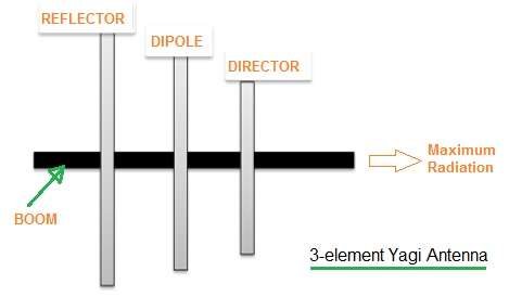
Figure 2.: The basic Yagi has three elements: a driven (active) dipole element with a passive reflector behind the driven element and a passive director in front of it, all mounted on a single boom. (Image: RF Wireless-World)
Yagi basics
The simplest Yagi antenna consists of three elements arranged along a support beam, usually metal but can be wood or fiberglass, as alternatives (Figure 2). Only the center element is electrically connected (designated as the “driven” element) and it is either a simple center-fed, half-wave dipole or a folded-dipole antenna. Behind the driven element is an insulated, somewhat longer reflector element; in front of it is a shorter, also insulated “director” element.
The reflector and director are sometimes referred to as “parasitic” elements in contrast to the active, driven element. Unlike the unwanted. undesirable parasitics that adversely affect the performance of components in RF and other circuits, these parasitics are critical to the antenna function. The operating principle is based on “tuning” of the reflector and director elements so they deliberately distort the electromagnetic (EM) field of the driven element.
The reflector is sized so it appears inductive in the bandwidth of interest. The induced EM currents in the driven element then are shifted in phase with respect to that element so they reflect the power away from the parasitic element. This causes the antenna to radiate more RF power in the direction opposite to parasitic element.
The reflector can be made inductive by adding a discrete coil, but in practice, it is almost always done the simpler and cheaper way: by making the reflector longer than the driven element. A standard rule of thumb is to make it 5% longer than the driven element.
In contrast, by making the parasitic element capacitive, the induced currents are shifted in phase so they direct the power radiated by the whole antenna in the direction of that element. Again, this can be done with a discrete capacitor, but it is almost always done by making it about 5% shorter than the driven element.
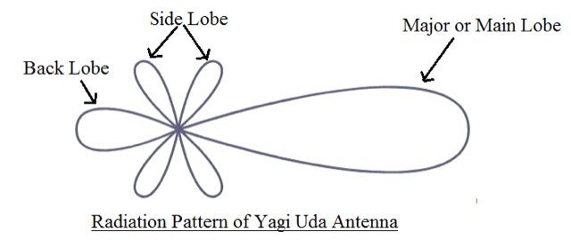
Figure 3. The generic radiation pattern of the simple Yagi shows high directivity and a front/back ratio along with modest side lobes. (Image: Electronics-Club)
The spacing between the driven and passive elements is also critical. As a starting point, spacing between the driven element and the reflector ranges from 0.23 wavelengths (λ) to 0.35 λ, while spacing between the driven element and the director is 0.125 λ to 0.15 λ. The result is a radiation pattern with high directivity and front/back ratio, as well as modest side lobes (Figure 3).
This basic Yagi appears as a balanced transmission line with a resistive impedance between 10 Ω and 40 Ω so a basic impedance-matching circuit is needed. The antenna can also be driven by an impedance-matching balun which also transforms an unbalanced coaxial transmission line to a balanced one.
Yagi flexibility
As you can see from the basic arrangement of the Yagi antenna, it offers many degrees of freedom. By changing lengths and diameters of the driven and parasitic elements as well as their spacing, the designer can vary and trade off antenna parameters of directivity, gain, front/back ratio, bandwidth, side lobes, and more.
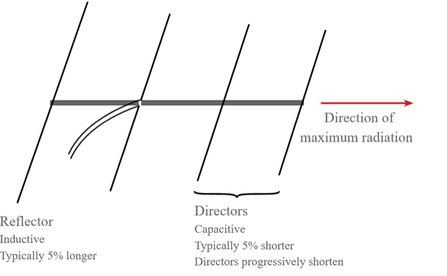
Figure 4. By adding additional passive director elements on a lengthened boom, the Yagi’s directivity and front-back ratio can be increased while side lobes are decreased. (Image: Electronics-Notes)
But the flexibility of the Yagi goes beyond those changes, as the Yagi is not limited to just three elements. By adding more director elements which get shorter and shorter as they are further in front of the driven element, the directivity of the antenna can be increased and the side lobes can be decreased (Figure 4).
The spacing between these additional director elements is also a fractional wavelength, offering another parameter that can be adjusted to further tune the Yagi performance to fit the application. Some Yagi antennas have a half a dozen or more director elements (Figure 5). Adding these additional elements increases the overall length of the main support. Using more reflector elements has little impact and so is rarely done.
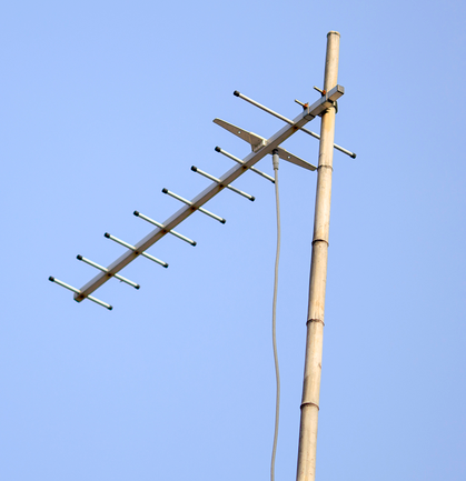
Figure 5. Adding more directors increases the boom length but has only a minimal impact on construction complexity, as seen by this Yagi antenna with seven directors. (Image: TreLink Communication Co.,Ltd)
Standard Yagi units are available for many parts of the spectrum, in addition to those designed expressly designed for OTA TV in the old analog bands or the newer digital bands. Many amateurs, hobbyists, and even designers of commercial RF products also build their own, as it is a very do-it-yourself (DIY) project using standard materials available at home-supply stores. Even if it is just as a prototype to test prior to contracting for mass-produced version, the DIY attributes of Yagi allow designers to quickly and easily fine-tune and optimize antenna performance versus tradeoffs in the intended application.
Conclusion
Antennas are the vital electrical circuit-to-wireless transducer and come in countless forms, with most based on the monopole and dipole configurations. There are many online resources related to antennas ranging from highly theoretical electromagnetic-field analysis to hands-on build/evaluate articles.
The PIFA is small and flat and provides excellent performance. While the PIFA can use the product’s circuit board for its ground plane, complete PIFAs are available as easy-to-install discrete components which offer layout and installation flexibility.
At almost 100 years old, the Yagi-Uda antenna is still widely used as it is one of the most flexible, versatile, and adjustable antenna arrangements. It is well-suited for applications where you need flexibility in choosing balances among gain, directivity, front/back ratio, and side lobes. This simple-looking antenna is available as a standard off-the-shelf item for many frequency bands, and it can also be easily custom-built, adjusted, and fine-tuned as needed.
EE World Related Content
- The microstrip antenna, Part 1: Basics
- The microstrip antenna, Part 2: Implementation
- What materials can be used to make miniature antennas?
- The basics of dielectric resonator antennas
- Practicalities of specifying 5G antennas for the IoT
- How distributed antenna systems bring cellular indoors
- What to consider when selecting a Wi-Fi antenna
- Getting one wire to do more, Part 4 – headphone wire as antenna
- Software tool helps designers place antennas in design
- 5 tips for designing with embedded antennas
- Metamaterials, mmWave antennas, 3D radar and holographic beamforming
External References
PIFA
- EnOcean, Application Note 102, “Antenna Basics – Basic Antenna Design Considerations for EnOcean based Products”
- Raymaps, “Antennas on Samsung Galaxy S“
- Antenna-Theory.com, “Inverted-F Antenna (IFA)
- Antenna-Theory.com, “PIFA – The Planar Inverted-F Antenna”
- European Union Digital Library, “Multiband Planar Inverted F Antenna (PIFA) for ISM,
WLAN and WiMAX Applications”
Yagi Antennas
- Wikipedia, “Yagi–Uda antenna”
- Electronics Notes, “Yagi Antenna Theory: Yagi Antenna Basics”
- Everything RF, “What is a Yagi Antenna?”
- Yagi, Hidetsu; Uda, Shintaro (February 1926). “Projector of the Sharpest Beam of Electric Waves” (PDF). Proceedings of the Imperial Academy. Imperial Academy. 2 (2): 49–52. doi:2183/pjab1912.2.49. Retrieved 11 September 2014.
- HamUniverse, “Basic Yagi Antenna Design for the Experimenter”
- Luxorion, “From Longwire to Yagi”


I would like to download a copy of this article
Steve,
Thank you for asking about downloading a copy of this article. We currently don’t have a PDF option for our articles. I’ll ask our web development team about it.