5G Technology World

  • 5G Technology and Engineering
  • FAQs
  • Apps
  • Devices
  • IoT
  • RF
  • Radar
  • Wireless Design
  • Learn
    • 5G Videos
    • Ebooks
    • EE Training Days
    • FAQs
    • Learning Center
    • Tech Toolboxes
    • Webinars/Digital Events
  • Handbooks
    • 2024
    • 2023
    • 2022
    • 2021
  • Resources
    • Design Guide Library
    • EE World Digital Issues
    • Engineering Diversity & Inclusion
    • Engineering Training Days
    • LEAP Awards
  • Advertise
  • Subscribe

Electromechanical Switches Cover Broad Frequencies from DC to 46 GHz

By Staff Author | September 3, 2015

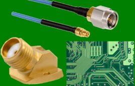
Pasternack introduces a large portfolio of in-stock general purpose multi-market coaxial packaged electromechanical switches for RF, microwave and millimeter wave applications. These new electromechanical switches are uniquely qualified for use in numerous applications including military communications, radar, commercial and military aviation, SATCOM, test & instrumentation, medical equipment and others.

Pasternack’s newest electromechanical switches consist of 134 connectorized designs that are guaranteed for 1 million life cycles. These new general purpose switches complement Pasternack’s existing family of 2M to 10M life cycle High-Rel Electromechanical Relay Switches, making the company’s in-stock RF switch portfolio the largest in the industry. These RF relay switches are available in a variety of different connector options including SMA, N Type, TNC and 2.92mm and are offered in popular configurations such SPDT, DPDT, SP4T, SP6T, SP10T and Transfer. Additional features available on specific models include Latching Actuators, Failsafe Actuators, Indicators, TTL Controls, Terminations, Pulse Latching and Hot Switching.

The new general purpose electromechanical switches from Pasternack cover frequency ranges from DC to 46 GHz and have power ratings ranging from 10 Watts to 275 Watts. These RF switches also boast high isolation up to 80 dB, switching speeds ranging from 15 ms to 50 ms and low insertion loss ranging 0.2 dB to 0.6 dB. All materials and finishes are in accordance with applicable MIL standards.

Filed Under: RF


Next Article

← Previous Article
Next Article →

Related Articles Read More >

Butler Matrix
Butler Matrix drives Wi-Fi and other phased-array antennas
Long-wire dipole antennas: still viable after more than a century
RemCom Wireless InSite 4.0
Software simulates RF conditions from the Earth to the Moon
FAQ on the Butler matrix for beamforming: part 2

Featured Contributions

  • Overcome Open RAN test and certification challenges
  • Wireless engineers need AI to build networks
  • Why AI chips need PCIe 7.0 IP interconnects
  • circuit board timing How timing and synchronization improve 5G spectrum efficiency
  • Wi-Fi 7 and 5G for FWA need testing
More Featured Contributions

EE TECH TOOLBOX

“ee
Tech Toolbox: 5G Technology
This Tech Toolbox covers the basics of 5G technology plus a story about how engineers designed and built a prototype DSL router mostly from old cellphone parts. Download this first 5G/wired/wireless communications Tech Toolbox to learn more!

EE LEARNING CENTER

EE Learning Center
“5g
EXPAND YOUR KNOWLEDGE AND STAY CONNECTED
Get the latest info on technologies, tools and strategies for EE professionals.

Engineering Training Days

engineering
“bills
5G Technology World
  • Enews Signup
  • EE World Online
  • DesignFast
  • EDABoard Forums
  • Electro-Tech-Online Forums
  • Microcontroller Tips
  • Analogic Tips
  • Connector Tips
  • Engineer’s Garage
  • EV Engineering
  • Power Electronic Tips
  • Sensor Tips
  • Test and Measurement Tips
  • About Us
  • Contact Us
  • Advertise

Copyright © 2025 WTWH Media LLC. All Rights Reserved. The material on this site may not be reproduced, distributed, transmitted, cached or otherwise used, except with the prior written permission of WTWH Media
Privacy Policy

Search 5G Technology World