Calibration is important in the measuring the installation effectiveness of fiber-optic cables. Fluke Fellows Seymour Goldstein and Jeff Gust explain why.
High-speed data connections in telecom networks and data centers rely on fiber-optic cables to move information. When we think of the “physical layer” of the protocol stack, we think of raw, unformatted bits formed though modulated light pulses — typically non-return to zero (NRZ) or four-level pulse-amplitude modulation (PAM4). The primary measurement for raw bits is bit-error-rate (BER) supplemented by eye-diagram measurements. Once we get above this layer, we begin to organize bits into packets and protocols.
To some, however, the “physical layer” has neither bits nor modulation. “We Consider BER as layer 2,” said Seymour Goldstein, Fellow at Fluke Networks in an interview with 5G Technology World. To Goldstein, the physical layer is the basic transfer of unmodulated light through a fiber-optic cable and its connectors. While fiber cables can transfer light over long distances, they still attenuate signal power. Some attenuation comes from the fiber itself while some comes from the connectors at the ends of the fiber. This attenuation reduces the signal-to-noise ratio of the data being transmitted, and the lower the signal to noise ratio, the higher the BER potential for the data.
Testing a cable means launching a known amount of light into the fiber and measuring how much light comes out the other end. In addition to testing for power and attenuation, fiber-optic links can bend, break, or suffer from other damage. Optical time-domain reflectometers (OTDRs) can measure the distance to a fault by sending a pulse of light into the fiber.
Because measuring power and distance to a fault are analog measurements, test equipment requires calibration. Jeff Gust, Chief Corporate Metrologist at Fluke Calibration shared information about calibration and measurement uncertainty during our discussion.
Fiber’s most common problem
Installation and daily use of fiber-optic links can add attenuation to a signal. “We see fiber interface cleaning as a common problem,” said Goldstein. “Inspection of a connection can show contamination that can lead to additional insertion loss and return loss.” Gust emphasized that point, saying contaminated connectors are the number one cause of failure in optical networks. “About 80% of networks have connector issues,” he said.
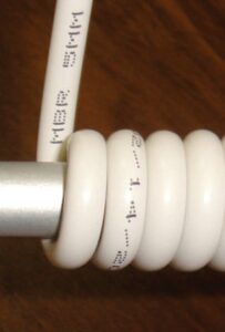
Figure 1. Bend-insensitive fiber-optic cables guide light through tighter bends than traditional cables. Image: Corning
In addition to connection issues, fiber-optic communication links are subject to excessive bends and kinks in the fiber. Fiber optics operate on the principle of total internal reflection, and so long as the bending of the fiber-optic cable remains less than the critical angle as defined by the type of core and cladding material of the cable, the optical signal will remain inside of the core of the cable, but if the critical angle is exceeded, some of the signal is lost by refracting into the cladding “Too much bend results in attenuation,” said Gust. Fiber manufacturers will specify a cable’s minimum bend radius and many now produce bend-insensitive fiber-optic cables that minimize losses from tight bends (Figure 1).
“Fiber is generally strong in the ‘pulling’ direction but not in the axial direction,” added Goldstein. “Problems can occur in datacenters when installed fiber gets pulled too tightly around a rack.”
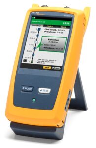
Gust noted that an OTDR (Figure 2) can tell you where there’s an excessive bend, kink, or break in a fiber. OTDRs can measure problems in fiber at distances to 120 km.
“With an OTDR,” added Goldstein, “we send a high-energy pulse of light into the fiber. The length of the pulse depends on the distance to be measured. For a long distances, the pulse length might be 10 µs to 20 µs. The pulse will propagate, and information will reflect back to the source (i.e., OTDR detector). We can identify kinks, loss, reflectance (return loss, Fresnel Reflection) all from a single-ended measurement.”
Optical measurements need calibration
To measure optical power and attenuation, the light source (laser for example in single-mode fiber testing) will send continuous wave (CW) light into the fiber. “There’s no modulation here,” said Goldstein. “Well, maybe 1 kHz to 2 kHz over short distances, which is used to help identify fibers in a multifiber cable.” An optical power meter at the other end measures optical power.
That’s where calibration comes in. The light source must produce a known light power and the power meter must measure that power within specified tolerances where those tolerances can vary depending on parameters such as wavelength.
Gust explained that an RF power sensor has calibration coefficients for different frequencies. As an example, he said that at 19 GHz, a sensor might have a calibration factor of 99.7 and at 26 GHz that factor might be 96.5. Fiber-optic power meters operate on a similar principle where there are calibration factors based on wavelength or attenuation levels.
Meter manufacturers will specify accuracy tolerances, which metrologists call “Instrumental uncertainty,” that a measurement will fall within some tolerance. Metrologists go further, adding a confidence level to that tolerance. Thus, an actual measurement value could be, for example, -20 dBm ±0.5 dBm with a 99% confidence level, meaning there’s still a 1% chance that the actual value is out of tolerance.
For measurements of the highest accuracy, calibration labs may need equipment that performs better than manufacturer specifications. “We have to do special characterizations to hold a tolerance to better than when manufactured,” said Gust. “We can characterize and understand the performance of an instrument over time. Understanding an instrument’s stability lets us achieve better measurements than an instrument was designed to achieve.”
Gust gave an example of a laser light source where a manufacturer might spec an 850 nm light source power at -20 dBm ±1 dB with a 3σ (99.7%) confidence level. “That might meet their advertised specs, said Gust, “but we might need ±0.2 dB tolerance when using this to calibrate other important equipment.”
“In metrology, history is everything,” said Gust. “We can use that history to predict how much a measurement instrument will drift over time. We have measurement standards that John Fluke Sr. purchased in 1962 and we have 60 years of history on them.”
“History means a lot,” he continued. Metrology is about getting enough data to have confidence in a measurement. For us to get better uncertainty and confidence in the field, we need smaller uncertainty coming out of the calibration lab. We also want high confidence coming from our transfer standards used to move measurements from the lab standard to a working standard that we use to calibrate equipment that goes into the field. That’s why we go to NIST to get perhaps the best calibration standard in the world to meet our needs. By starting with better measurements, we can then push those measurements down to equipment sold into the field.”
Without metrology — calibration, uncertainty, traceability — there would be no confidence in measurement. Because we have well defined and mature standards for calibrating OTDRs and optical power meters, engineers can expect uniformity among vendors. As we have witnessed with visual inspection equipment, however, relying on automated analysis microscopy, variability among vendors exists. Part of that reason is the metrology aspects of an agreement on a traceable calibration artifact.



Tell Us What You Think!