The infrastructure needed to deliver cost effective, reliable, and secure timing throughout cellular networks needs proper architecture, design, and management. Tighter time accuracy demands for 5G networking equipment requires reliable and robust timing architectures that guarantee network performance.
As networks evolve from using communication links based on frequency division duplex (FDD) to time division duplex (TDD), the need for not only frequency but accurate phase and time synchronization arose. Equipment that operators deployed in TDD networks rely on a combination of GNSS, Synchronous Ethernet (SyncE), and the IEEE-1588 Precision Time Protocol (PTP) to deliver accurate frequency, phase, and time across the network.
The new 5G RAN architecture introduced in 3GPP Release 15 split the baseband unit (BBU) and remote radio head (RRH) into Centralized Units (CU), Distributed Units (DU), and Radio Units (RU). This new RAN architecture creates a disaggregated and virtualized network that allows carriers to realize efficiencies and cost savings throughout the network.
Disaggregation gave rise to the enhanced common public radio interface (eCPRI), which connects the DU and RU. This interface provides distinct advantages over the CPRI links previously used to connect the BBU to remote radio head (RRH). Because eCPRI is packet based, synchronization with the RU now occurs by employing PTP and SyncE.
Additionally, the Open RAN movement has standardized hardware and interfaces that are based upon the 3GPP recommendations. The O-RAN Alliance has defined four options for the distribution of timing through the fronthaul network. In all four configurations, the RU either receives timing from the DU or from a nearby Primary Reference Time Clock (PRTC). Despite the various timing flows, the key functions needed to support timing distribution through an O-RAN network are still based on SyncE, IEEE-1588, and GNSS.
Timing Standards
Various timing recommendations have been put in place so that each network element meets certain frequency, phase, and time requirements, ensuring proper end-to-end network operation. For TDD cellular networks, the basic synchronization service requirement defined by the 3GPP for time synchronization was set to 3 µsec between base stations. The International Telecommunication Union Telecommunication Standardization Sector (ITU-T) maintains a set of recommendations that define the absolute maximum time error (max|TE|) error between a common point and the end application based on the 3GPP requirement, which translates to ±1.5 µsec.
GNSS became the dominant means for sourcing time in TDD networks through PRTCs. One approach was to co-locate the GNSS receivers at the radio site, but this requires good line of sight to the sky for reliable operation. Radios located indoors or in locations that prohibit clear line of sight cannot take advantage of a local GNSS source. GNSS is also subject to outages due to line-of-sight disruptions such as weather events, or targeted attacks from spoofing or jamming. The sheer number of planned 5G NR sites make the cost of installing and maintaining GNSS sources difficult for carriers to absorb.
The need for a more accurate PRTCs in addition to the concerns about the reliability and cost of deploying GNSS has led to the definition of an enhanced primary time clock, ePRTC. The ePRTC can initiate time through GNSS or another network standard time source traceable to UTC. After acquiring the time, an ePRTC then uses a cesium or better atomic reference oscillator to maintain a reliable, highly accurate and stable time reference for the network. The use of an autonomous atomic timed reference provides a level of immunity to disruptions and provides stable holdover for up to 14 days. The time accuracy of the ePRTC is ±30 nsec to UTC, a major improvement of the ±100 nsec accuracy specified for the previous PRTC. This improved accuracy meets the demanding network requirements of 5G NR.
The Telecom Boundary Clock (T-BC) and destination clock (T-TSC) are other crucial elements that ensure the network accurately propagates time. The T-BC typically resides in a switch or router and is responsible for recovering time from upstream links and passing it to downstream links. The Ethernet equipment clock (EEC), or SyncE, within the T-BC/T-TSC provides a stable and accurate frequency reference traceable to the primary reference clock (PRC/PRS) with a frequency accuracy of 0.01 pbb. Using SyncE alongside PTP offers several advantages for accuracy and cost improvements. The SyncE reference, which is more accurate than the local oscillator, can drive the PTP engine. This lets the PTP engine filter larger amounts of packet delay variation (PDV), which improves the overall phase accuracy.
Basic time accuracy requirement
For TDD network deployments, the end-to-end network limit for time accuracy is ±1.5 µsec as detailed in G.8271. From this value, a timing budget that defines the performance required for each network element is derived, thus meeting the end-to-end limit. The clock equipment specification, defined in G.8273.2, breaks down the time error into constant and dynamic time error. Constant time error (cTE) represents error that occurs from inherent delays in the network. These errors cannot be filtered; they accumulate as time propagates through the network. Dynamic time error (dTE) is error derived from high- or low-frequency noise. Proper filtering of the network reference clocks can reduce these errors.
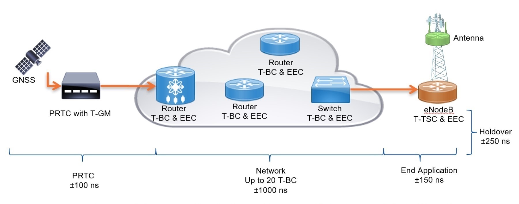
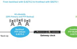
Figure 1. To meet latency specs, a network must maintain ±1.5 µsec timing limits where the total spreads out over the network elements.
The ±1.5 µsec basic network limit is divided amongst the network elements. The allowable time-error budget for each network element for the 4G network is shown in Figure 1. The PRTC with T-GM is limited to ±100 nsec of error and each T-BC is given a max|TE| based upon the class level. Table 1 details the max|TE| allocated for each clock class.
| Class | max|TE| | cTE |
| A | 100 nsec | 50 nsec |
| B | 70 nsec | 20 nsec |
| C | 30 nsec | 10 nsec |
| D | For further study | For further study |
Table 1. G.8372.2 T-BC and T-TSC clock equipment time-error limits.
Additionally, a cTE limit is assigned for each T-BC depending on the class level. Network link asymmetries and the end application each receive assigned maxTE values as well. Networks supporting up to 10 hop class A T-BC or 20 hop Class B T-BCs are sufficient to meet the basic network limit.
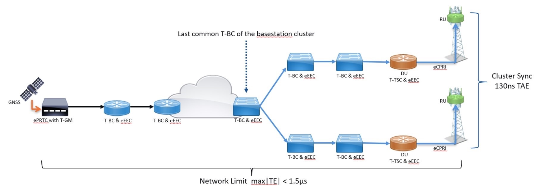
Figure 2. T-BCs in 5G networks have a max|TE| based upon the class level.
Advanced time-accuracy requirements
The 1.5 µsec basic end-to-end requirement is the same for 4G and 5G networks. However, certain radio technologies such as coordinated multipoint, carrier aggregation, or massive MIMO, place more stringent limits on the time error. Figure 2 shows the concept of relative time error, which describes the time error of the end applications traceable to the last common point of a radio cluster. The advanced time accuracy requirements needed for NR deployments reduced the allowable relative time alignment error (TAE) to 130 nsec, or ±65 nsec maxTE, within a cluster.
In addition to the new ePRTC discussed earlier, Table 1 also lists new classes of T-BC and T-TSC clocks that have been defined by the ITU-T to support these tighter limits. The G.8372.2 class C and the emerging class D requirements further constrain the allowable TE each element can introduce.
Each class C and class D element is required to support the enhanced Ethernet Equipment Clock (eEEC) standard as defined in G.8262.1.
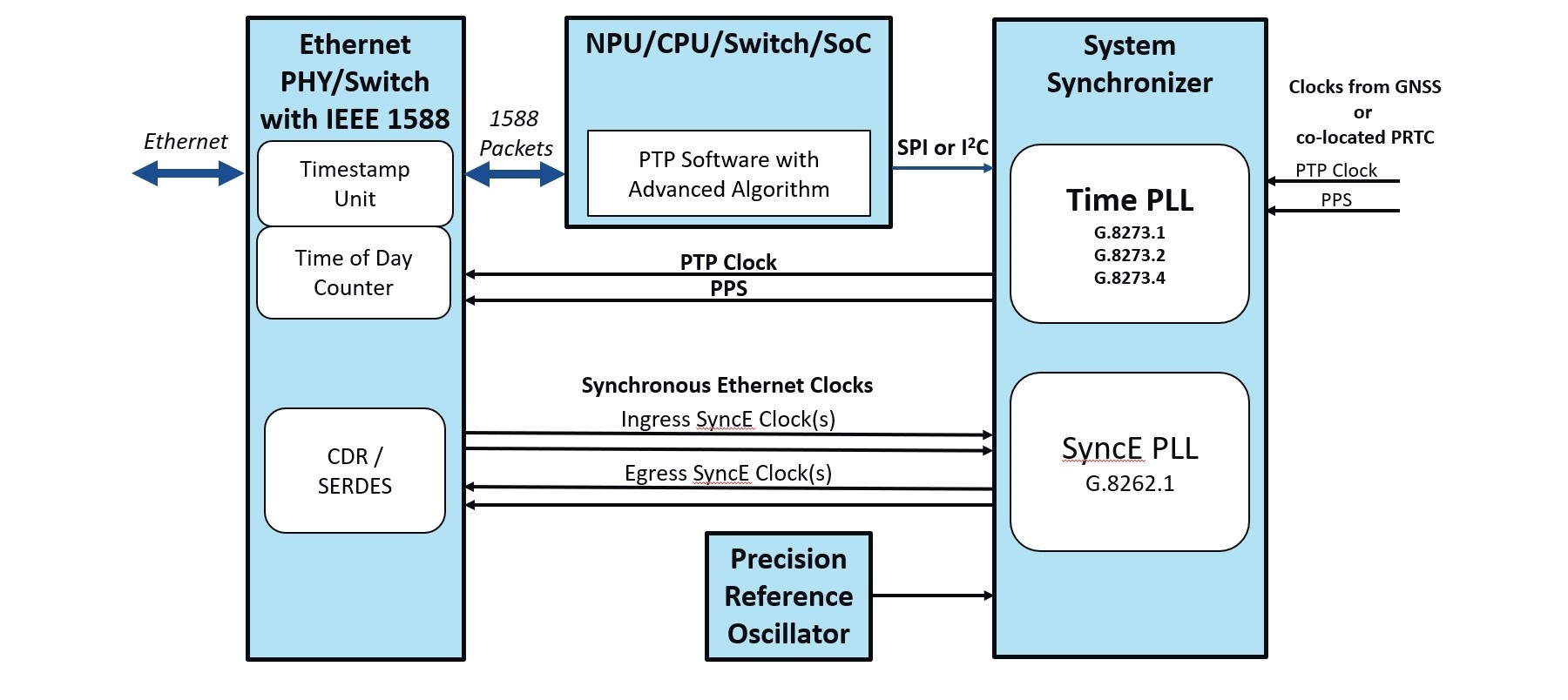
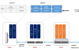
Figure 3. 5G network timing relies on switches and synchronizers.
Design for timing
Figure 3 shows a typical block diagram of the key components used to maintain, manage, and distribute timing in equipment design. It can be used as a guide when designing for CU, DU, or RU applications. The main function in the timing design is a system synchronizer comprised of one or more sophisticated phase-locked loops (PLL) that offer the functionality necessary to provide precise frequency and time synchronization. These synchronizers are responsible for clock monitoring, reference switching, filtering, and syntonizing accurate clocks that keep equipment synchronized to network time. Multiple PLLs within the same synchronizer allow for support of SyncE, PTP, and additional time requirements. Synchronizers supporting multiple inputs and outputs can monitor and syntonize clocks for various interfaces.
For SyncE support, one or more recovered clocks connect to the system synchronizer, which will qualify and manage the various input references. The synchronizer selects one recovered clock as the primary clock and the SyncE PLL will filter the clock before redistributing it to the egress nodes. If support for the enhanced Ethernet Electrical Clock (eEEC), as defined in G.8262.1 is needed, it is critical to ensure that the SyncE recovered clock can be quickly squelched on a Loss of Signal (LOS) condition. This ensures that the short-term and long-term phase transient limits of G.8262.1 can be satisfied.
Proper implementation of PTP requires accurate timestamping capabilities and dedicated software to properly maintain precise time synchronization. To minimize delay, timestamp units should reside as close to the edge of the box as possible. For Class B equipment, a timestamp unit with 10 nsec of accuracy is sufficient. To meet Class C clock requirements, timestamp units should have an accuracy of 4 nsec or better. A PTP software stack and, most crucial, a robust time algorithm is needed to handle PTP packet communication, process timestamps, and make frequency and phase adjustments to the Time PLL inside of the system synchronizer. The Time PLL could also be locked to pulse per second (PPS) inputs from local PRTCs or other equipment that supply PPS references.
Finally, a precision oscillator provides the frequency base at startup and ensures stable operation in cases of network disruption. Not all use cases will require robust holdover capabilities, but the further into the core of the network the equipment will be placed, the more stable the oscillator needs to be.
Class C & class D design considerations
Take care when designing the timing architecture in systems required to meet the class C and D requirements. In addition to improved timestamp accuracy and the need of providing squelching capability for the ingress eEEC on LOS conditions, you can apply calibration techniques to properly manage the cTE and dTE within a given design. Provisioning for on-board or in-system calibration has become more popular and necessary as engineers drive to minimize the time error that equipment introduces. The identification of potential sources of cTE due to process, temperature, and voltage need to be taken into consideration at time of component selection.
You need to minimize delays introduced by buffers, FPGAs, timestamp units, or other devices in the timing path and, if possible, correct then with calibration techniques at the board and/or system level. Input-to-output propagation delays through buffers and other devices can be allocated for by providing a feedback path back to system synchronizers that allow for dynamic calibration of delay. It is no longer sufficient to solely focus on the input-to-output delay of a box because of the relative time-error requirement introduced by the advanced time accuracy limits. Pay attention to the output-to-output alignment for each PPS output within a system. Additionally, for chassis equipment, the line card PLL bandwidths for each output should be the same or programmed as high as possible to ensure the equipment handles any phase changes as identically as possible across all outputs.
Synchronizers, timestamping PHYs, and switches can compensate for known delays inherent in board designs. From a board level, static calibration techniques can compensate for trace delay and propagation delays on a per-output or per-port basis. Synchronizers can provide per-input trace delay and buffer compensation, picosecond phase adjustment resolution, per output trace delay compensation, and per-input or per-output cable delay compensation for GNSS or G.703 1PPS interfaces. Additionally, advanced timestamping devices provide per-port timestamp calibration with picosecond resolution. These features offer flexibility to measure and correct for phase error within a system to ensure TE is minimized.
Conclusion
Synchronization requirements and capabilities continually evolve to drive the ultra-low latency, high bandwidth, and advanced new radio applications for 5G and beyond. Satisfying the new enhanced standards for time accuracy in network equipment requires careful planning of the timing architecture.
Reference
The Enhanced Primary Reference Time Clock (ePRTC) as a Solution for GNSS Vulnerability, September 2020, https://ww1.microchip.com/downloads/en/DeviceDoc/00003630A.pdf
 Darrin Gile is a Senior Technical Staff Engineer for Microchip Technology’s timing and communications business unit, with more than 26 years of experience in the semiconductor industry. For the past 20 years he has held field applications and business development roles assisting clients with network synchronization and advanced timing applications. He specializes in customer engagements related to Synchronous Ethernet and IEEE-1588. Darrin holds a Master of Science degree in electrical engineering from the Georgia Institute of Technology.

Tell Us What You Think!