5G brings higher data rates and a need for more efficient power amplifiers. Understand and calculate a PA’s efficiency.
Radio communication systems steadily improve data rates and overall system performance. With that higher performance comes increasing pressure on power consumption. A recent industry report [Ref 1] concluded that power consumed by a typical 5G base station will be 12 kW compared to 7 kW for an LTE base station. That’s about 5 toasters worth of additional power being used. (A typical 2-slice toaster consumes about 1000 W.)
System designers often fret about power consumption. In battery-powered mobile devices, the talk time from one charge depends on battery capacity and the power consumed by the device. Lower power means longer operating time. At the base station, battery power may not be the issue but the cost of energy in the network can add up. And, of course, wasted power in any device generates heat which must be dissipated.
Power Amplifiers
Power amplifiers (PAs) are one significant consumer of power in a wireless system, so amplifier efficiency is important. Figure 1 shows a PA producing output power (Pout) based on the input power (Pin) and the supplied DC power (Pdc).
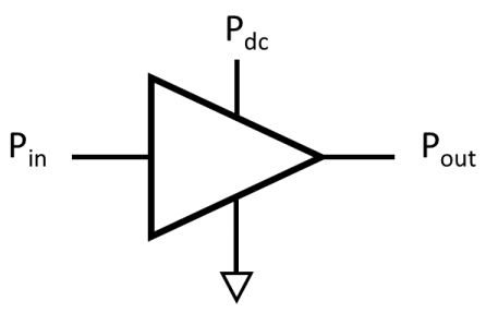
Figure 1. The basic PA produces output power from the input power and DC power supply.
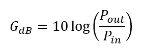
Engineers usually express an amplifier’s power gain in decibels:
 Power-Added Efficiency (PAE) expresses the overall efficiency of the power amplifier, including the effect of the input power.
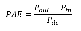 PAE is usually expressed as a percent. For example, a power amplifier having an output power of 10 W, an input power of 0.5 W and DC power of 30 W would have a PAE = (10-0.5)/30 = 32%. The power gain of this amplifier is GdB= 10 log (10/0.5) = 13 dB.
Power efficiency (PE) is another parameter used to describe amplifier efficiency, ignoring the effect of the input power. In this case, the efficiency is defined simply in terms of the output power and the supplied DC power.
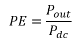 When power efficiency is focused on a single transistor it is sometimes called the drain efficiency (FET device) or collector efficiency (Bipolar transistor). This usage reflects the fact that the DC power is largely determined by measuring the current through the drain or collector, multiplied by the DC power supply voltage.
Note that when the gain of the amplifier is reasonably high, the input power fades in importance causing PAE to be roughly the same as PE.
Peak-to-Average Power Ratio
Variation in the input signal can affect the practical efficiency of a power amplifier when in use. Modern digital modulation methods often result in signals that vary considerably in instantaneous power. (See Digital modulation basics, part 1). Figure 2 shows the instantaneous power level of a signal with high peak power (Ppeak) compared to its average power (Pavg). One way to describe this “peakiness” of the waveform is the peak-to-average power ratio (PAPR), expressed in decibels.
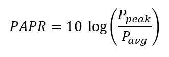
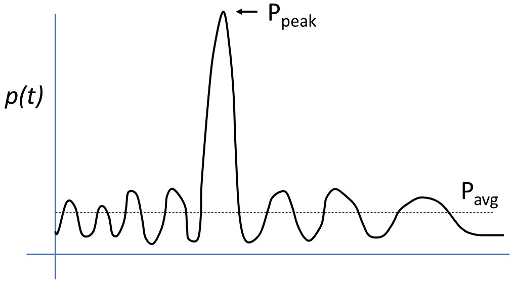
Figure 2. A bursty signal has high peak power relative to the average power.
Amplifier designers like constant power levels so they can tweak the amplifier to perform best at that particular level. Figure 3 shows the PE as a function of output power for a typical power amplifier. Amplifier efficiency tends to drop at low power levels. For our purposes, the shape of the curve is more important than the specific values. The PA must handle the peak power, but the signal’s average power mostly determines its practical power efficiency. Fig. 3 also shows the operating point with best efficiency, where we would like the amplifier to operate. Unfortunately, the PAPR of the signal causes you to move the operating point to the left so that the peak power doesn’t overdrive the amplifier.
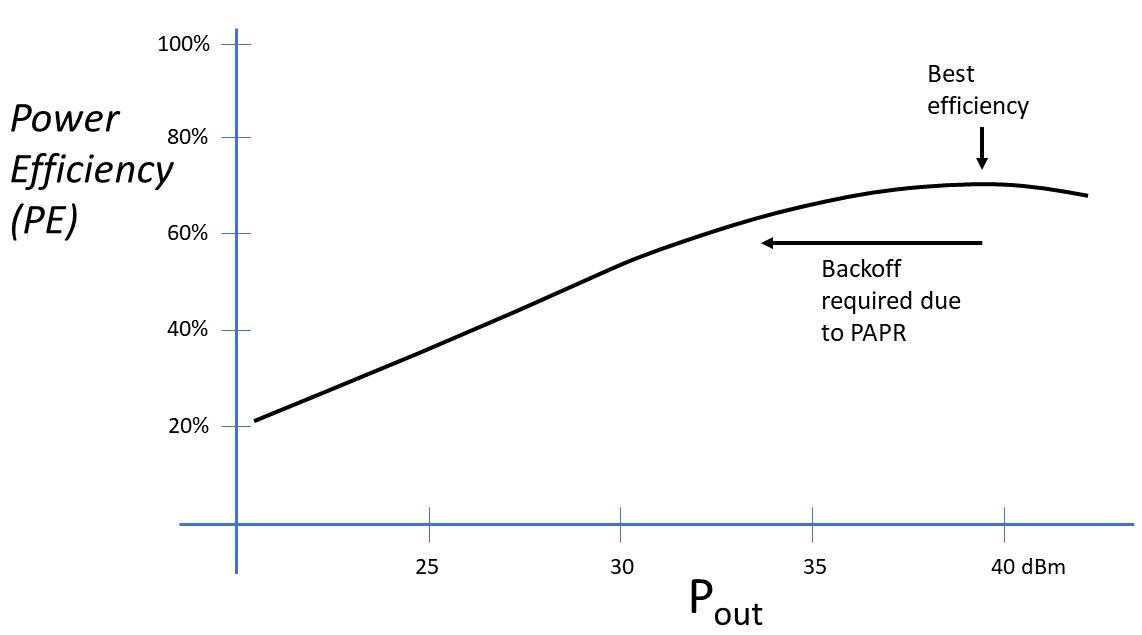
Figure 3. The efficiency of a power amplifier varies with output power.
Design Options
Backing off on the operating point (and output power) of the amplifier is an obvious solution to the problem of high PAPR. However, the efficiency of the amplifier will suffer. Fortunately, RF engineers have developed two methods that can adjust the amplifier operating behavior in real time and improve the efficiency.
Both methods were first proposed in the 1930’s but are now commonly-used design approaches in the 21st century. These amplifier design methods are:
- Envelope Tracking Amplifier: The input signal dynamically controls the power supply voltage of the amplifier.
- Doherty Amplifier: A two-path amplifier that responds to peaks in the input signal when required.
We will take a closer look at these two methods in future articles.
References
1. “5G Power: Creating a green grid that slashes costs, emissions & energy use,” Huawei, Chen Dongxu, July 29, 2020, https://www.huawei.com/us/publications/communicate/89/5g-power-green-grid-slashes-costs-emissions-energy-use.
2. “How to Design an RF Power Amplifier: The Basics”, Keysight Technologies, YouTube video,
https://youtu.be/WAingaHfBMs.
 Bob Witte is President of Signal Blue LLC, a technology consulting company. Bob has held many positions in R&D, technology planning, strategic planning, and manufacturing for Keysight Technologies, Agilent Technologies and Hewlett-Packard Company. Inside, he is just an engineer that loves to see innovative products solve real customer problems. Bob is the author of two books on test and measurement instrumentation: Electronic Test Instruments (2nd Edition) and Spectrum and Network Measurements (2nd Edition).
Related articles
- IMS 5G Summit: Design challenges remain (part 1)
- IMS 5G Summit: Design challenges remain (part 2)
- 5G is hot, keep your components and systems cool
- The RF power amplifier, Part 1: Functions
- The RF power amplifier, Part 2: Considerations
- Digital Modulation basics, part 1
- Digital Modulation basics, part 2

Tell Us What You Think!