Basic RF measurements go a long way toward characterizing today’s communication systems.
RF field engineers and technicians who work in communications systems such as commercial telecom networks, satellite communications systems, public safety, and military/aerospace systems often measure a variety of signals in cables, antennas, and direct over-the-air (OTA) systems. A basic understanding of RF measurements will help you with these tasks..
Installing and maintaining communications systems often requires in-field verification and may require adjusting components such as filters, duplexers, or antennas. As OTA systems become more complex, field engineers often need handheld a instrument that performs the tests necessary to keep a network up and running and they must know how to use it. An understanding of the measurement basics and technologies gives you the tools to keeping RF networks running.
Field engineers and technicians often perform these common measurements:
- Real-time spectrum analysis (RTSA);
- Noise figure measurements;
- Cable and antenna tests (CAT);
- Over-the-air (OTA) testing;
- Electromagnetic field (EMF) exposure evaluation.
Signal interference over wireless networks can result in poor signal quality, which leads to dropped links or choppy audio. Interference also affects wireless devices from car radios to mission-critical applications such as public safety.
A traditional swept-spectrum spectrum analyzer needs time to process and display waveforms. Intermittent interference may arise during this time, which might not appear in the trace. Furthermore, long-duration signals can mask weak signals that cause interference. Real-time spectrum analyzers, which capture and digitize signals, then apply FFT techniques, can reveal intermittent signals missed by traditional spectrum analyzers.
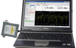
Detecting and troubleshooting interference often challenges RF field engineers and technicians. Interfering signals can hide under carrier signal. To see any interference, you must turn off the carrier transmitter to find any other signals in the same frequency channel, but that’s not always possible nor practical. Turning off the carrier signal tends to be intrusive and can disrupt normal communication services. Besides, under many circumstances, turning off serving transmitters is not viable, depending on the nature of the services such as base station testing. Fortunately, RTSA profiles over-the-air characteristics, detecting hidden interference under the serving carrier. The figure shows three interference signals hiding under the main carrier.

The left trace shows three interference signals hidden under the main carrier. The right trace zooms out to let you see more of the overall frequency content.
In the complete article, “A day in the life: Five RF measurements for field engineers” at Test and Measurement Tips, Keysight’s Sarah Gross covers the remaining four topics. Click between the quotes to read the full article.
Tell Us What You Think!