Millimeter wave signals provide wider bandwidths and higher data rates than signals at lower frequencies. Take a look at the overall signal chain that falls between the antenna and the digital baseband.
5G new radio (5G NR) adds mmWave frequencies to cellular devices and networks. With that comes RF-to-baseband signal chains and components not needed at sub-6 GHz frequencies. While mmWave frequencies technically span 30 GHz to 300 GHz, for 5G purposes mmWave covers 24 GHz to 90 GHz, though typically topping out at around 53 GHz. Originally conceived to bring higher data rates to smartphones in cities, mmWave applications have shifted to high-density use cases such as stadiums. It’s also finding use in fixed-wireless access (FWA) internet services and private networks.
Key benefits of 5G mmWave
5G mmWave’s high bandwidth transports massive amounts of data (10 Gb/sec) due to a channel bandwidth of up to 2 GHz (without carrier aggregation). This feature is optimum for networks with large data transmission needs. 5G NR also makes low latency possible because of higher network speeds between the 5G radio-access network and the network core. LTE networks had a 100 ms latency as where 5G networks have a latency of just 1 msec.
What’s in a mmWave signal chain?
The RF front end (RFFE) is typically defined as everything between the antenna and the digital baseband system. The RFFE is typically known as the analog-to-digital or RF-to-baseband portion of a receiver or transmitter. Figure 1 shows an architecture known as direct conversion (zero IF) where the data converters operate directly on the RF signal.
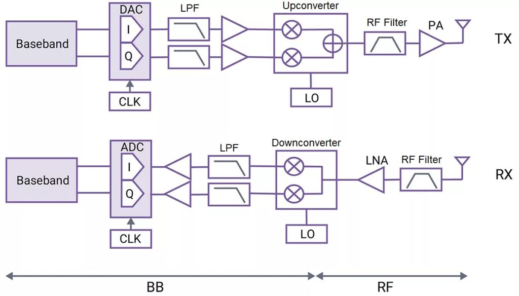
Figure 1. This 5G mmWave front-end signal chain architecture uses direct RF sampling; no IF needed (image: Synopsis).
The mmWave signal chain consists of an RF ADC, RF DAC, low-pass filters, a power amplifier (PA), a digital downconverter and upconverter, RF filters, a low noise amplifier (LNA), and a digital clock oscillator (CLK). A phase-locked loop/voltage-controlled oscillator (PLL/VCO) provides a local oscillator (LO) for the upconverters and downconverters. A switch (shown in Figure 2) connects the antenna to the receive or transmit signal chains. Not shown is the beamforming IC (BFIC), also known as the phased-array chip or beamformer. The BFIC takes the signal from the upconverter, then splits it into channels. It also has an independent phase and gain control on each channel to steer the beam.
When operating in receive mode, each channel will also have an independent phase and gain control. When the downconverter becomes enabled, it receives the signal puts it through the ADC. On the front end, there is an integrated PA, LNA, and finally the switch. The RFFE enables the PA or the LNA depending on whether it is in transmit or receive mode.
The transceiver
Figure 2 shows an example of an RF transceiver that uses an IF stage between the baseband and a mmWave wave band of 24.25-29.5 GHz. This architecture uses 3.5 GHz as the fixed IF.
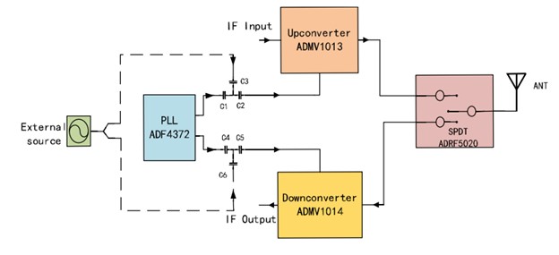
Figure 2. This image shows an architecture of a transceiver module based upon a superheterodyne architecture (image: IEEE, [4]).
Hybrid beamforming
Because mmWave signals have such a short reach, 5G uses beamforming and phased-array antennas to focus a signal on a target. Hybrid beamforming will combine analog hybrid beamforming, along with digital precoding, to intelligently create the patterns transmitted through a large antenna array shown in Figure 3. That same technique is used at the receiving end to create desired receiver patterns.
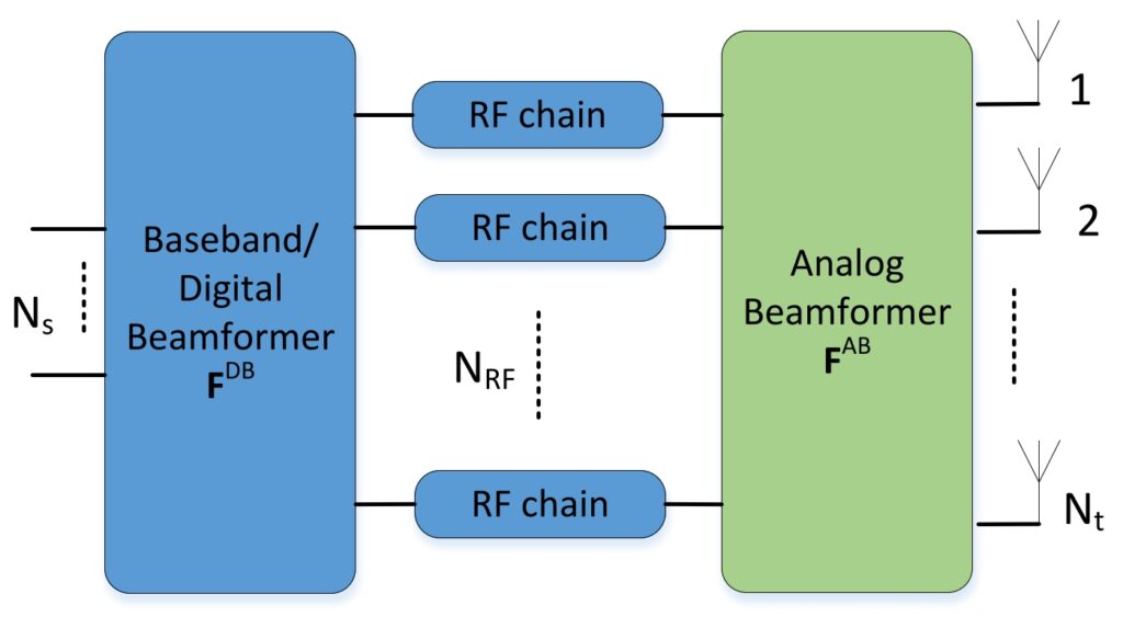
Figure 3. A hybrid beamforming structure for the mmWave transmitter uses digital precoding and analog beamforming (image: IEEE).
Deploying a 5G wireless infrastructure will greatly benefit service providers as well as consumers. The key markets served are cellular broadband and 5G communication modules to enable the Industrial Internet of Things (IIOT). This article has focused on the mmWave aspects of 5G. Future articles will follow on this topic and will focus, in more depth, on individual elements in the 5G mmWave signal chain.
References
[1] What is the 5G RF/mmWave signal chain?
[2] Analog Devices mmWave 5G Signal Chain
[3] 5G mmWave Wireless Communications | Analog Devices
[4] Study of 28 GHz Transceiver Module Integrated With LO Source for 5G mmWave Communication
[5] A Survey on Hybrid Beamforming Techniques in 5G: Architecture and System Model Perspectives


Tell Us What You Think!