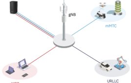
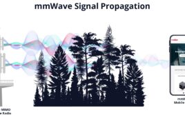
Today’s 5G system capacity requirements created the need for massive multiple-input multiple-output (MIMO) systems. Massive MIMO represents a major addition to 5G. Massive MIMO enables dynamic user-focused transmission and spatial multi-user MIMO (MU-MIMO), an essential functionality for providing high data rates over large areas. Figure 1 shows how cellular applications have changed.
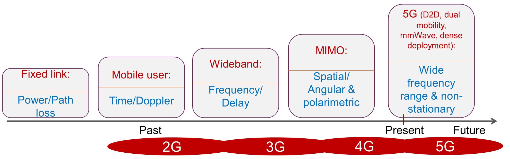
Figure 1. Communication systems continue to change and grow. 5G adds mmWave frequencies and beamforming, which adds complexity.
Sub-6 GHz massive MIMO base stations typically feature 16 to 32 antenna ports per array, each controlling a subarray of multiple antenna elements. MU-MIMO technology uses MIMO and beamforming to share base station capacity among multiple users over full 3D angular range. Ensuring massive MIMO performance requires testing base stations under different situations and conditions.
Performing MIMO testing using real-world conditions is critical for successful 5G deployments. Such real-world conditions include noise and interference from users and cells, propagation delay, frequency and Doppler for mobility, multipath fading and spatial separation for 5G cell capacity, and antenna beams and polarization for spatial separation.
Remember that massive MIMO technology is only effective when the number of base station antennas is much greater than the number of devices. Realizing its full benefit also requires the uplink and downlink channel conditions be equivalent.
But wait, there’s more: 3rd Generation Partnership Project (3GPP) standards do not provide beamforming tests for either user equipment (UE) or base stations, even though it is one of the new features that improve performance over 4G networks. 3GPP defines channel models but does not provide test scenarios. So, how do we test the end-to-end performance of massive MIMO UEs and base stations if such an essential part of the functionality is not included? Several new methods have been proposed that use channel models. First, a quick refresh on channel modeling is helpful.
Channel Modeling Basics
A radio channel (Figure 2) consists of three components: a transmitter antenna, a receiver antenna, and the propagation channel. It is characterized in four domains: time, frequency, space, and polarization. Mobile multipath will cause disruption and time variability in all domains.
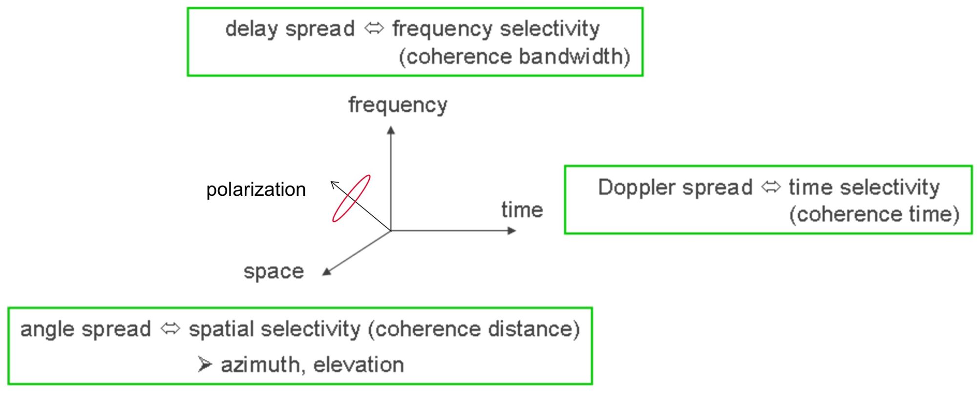
Figure 2. Radio channel dimensions consist of time, frequency, space, and polarization. Each aspect plays a role in signal quality.
Beamforming in a radio channel can use digital or analog techniques, or a hybrid. Digital beamforming features separate RF chains to each antenna and weights that are modulated directly to the transmitted signal in the baseband. The beamformer is not part of the antenna system, and thus not part of the radio channel.
In contrast, analog beamforming has just a single RF chain that feeds multiple antenna elements, splitting the signal. The weights are modulated on the radio frequency. The beamformer is part of the antenna system, which means that the beamformer is a part of the radio channel.
Hybrid beamforming is a combination of both principles with digital weights steering several analog beamforming arrays.
Channel models have increased in complexity over time, following the evolution of communication systems:
- Fixed links only required modeling for received power or path loss.
- 2G brought mobile users, resulting in radio channel conditions that vary with time and are subject to the Doppler effect.
- Wideband systems added channel considerations for frequency and delay.
- 4G multi-antenna techniques added antenna characteristics to the channel models including spatial/angular and polarimetric.
5G further increases channel model complexity by including these aspects and adding new ones, using beamforming and millimeter-wave (mmWave) frequencies.
Overall, channel models can be segmented into three categories. The geometry-based Stochastic channel model (GSCM, Figure 3) is the de facto modeling approach in the 3GPP standards. The antennas and the propagation channel are defined separately and combined mathematically. The user specifies both the transmit and receive antennas by defining the antenna array geometries and radius patterns. The propagation channel is characterized by parameters that come from distributions based on measurements and are specified in the standards.
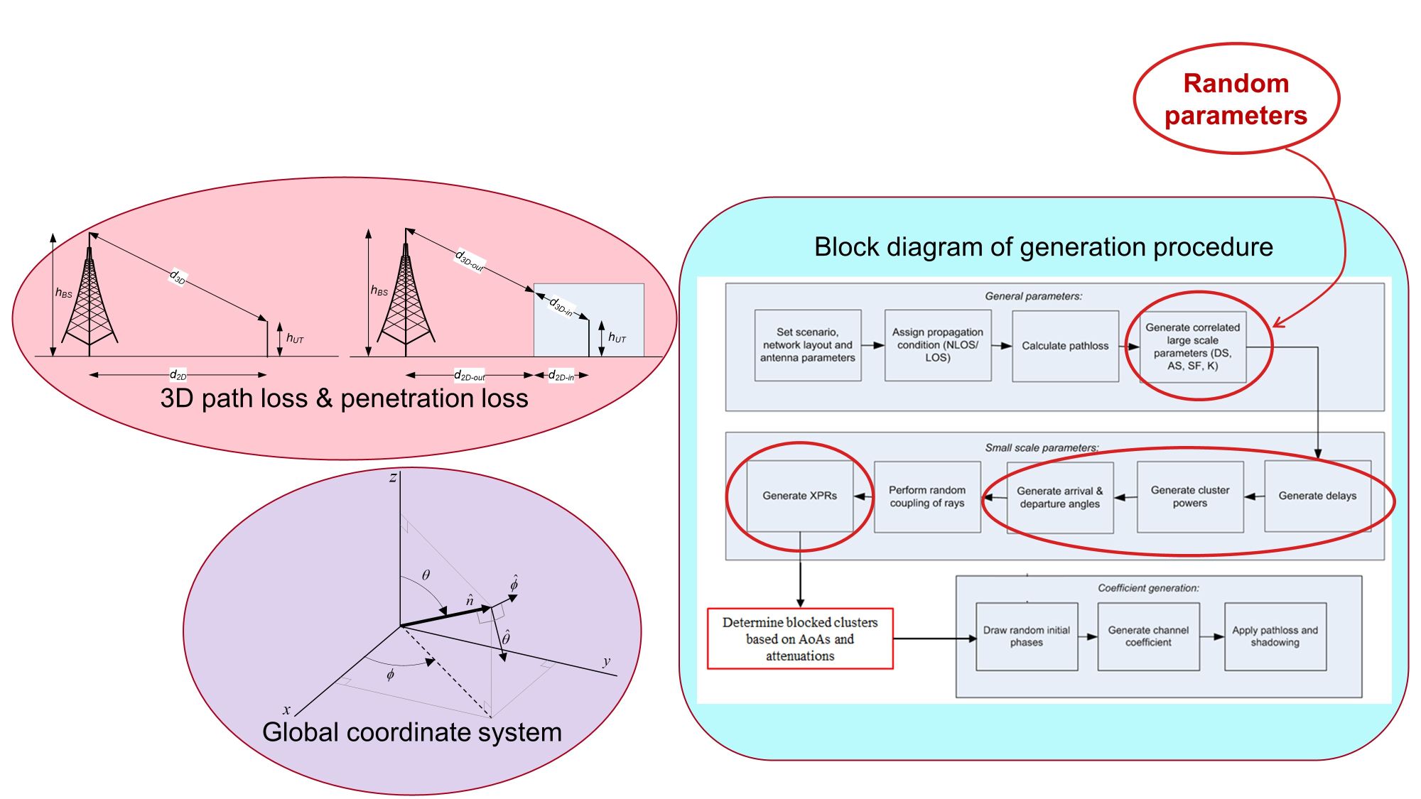
Figure 3. GSCM model example from 3GPP TR 38.901 takes path loss and penetration loss into account.
The map-based model (Figure 4) is a deterministic channel model based on ray tracing. Cartesian coordinates indicate a building’s corners and heights. Rectangular surfaces represent building walls. The map also includes random objects. Ray tracing is used to discover path waves. The model uses textbook formulas to compute reflection, diffraction, and scattering coefficients. Propagation parameters and antennas are embedded as they are in the GSCM channel model.

Figure 4. Map-based model example takes building shapes and heights into account.
The dynamic-geometry-based channel model (DGCM) is an extension of the GSCM model. This model (Figure 5) uses Cartesian coordinates to specify the locations of base stations and waypoints for a UE route. The UE then travels through the specified locations.
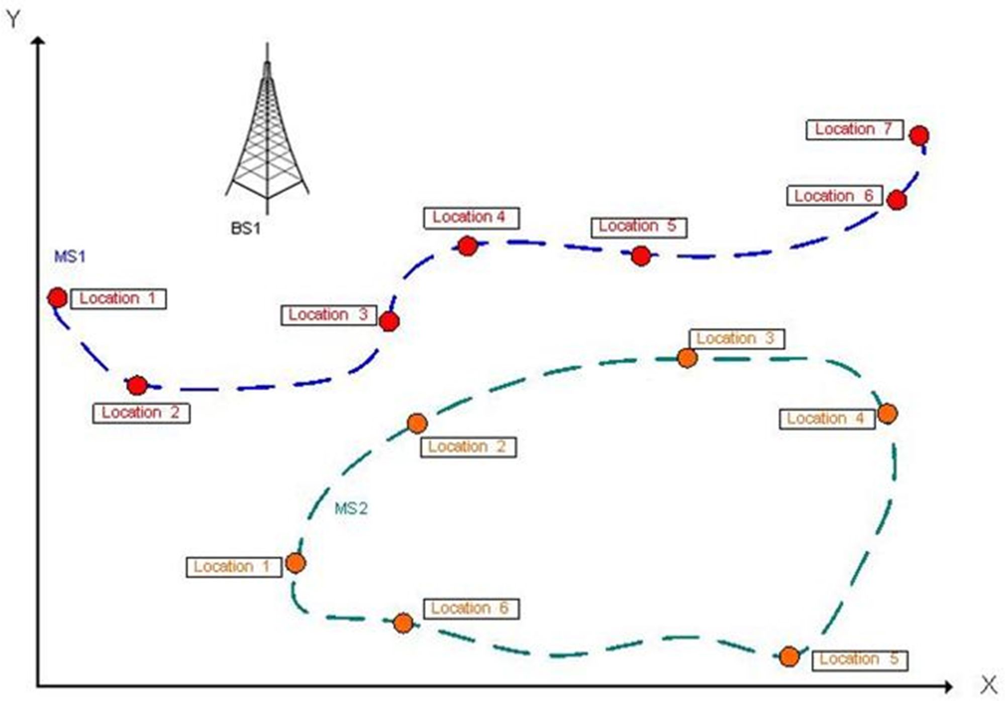
Figure 5. The DGCM model principle is based on Cartesian coordinates.
Many parameters are used to define each location including the following (Figure 6):
- Propagation parameters like the number of clusters, cluster delay, and cluster powers.
- Link parameters such as velocity and orientation of the UE antenna.
- Other phenomena that happen between the waypoints.

Figure 6. Pure line of sight (LOS) scenario with directive antennas that shows the smooth evolution of gain, Doppler, and delay profiles, making the antenna gain effect clearly visible.
All these aspects are interpolated linearly over time to generate smooth, dynamic, evolving radio channel conditions, making this model well suited for beamforming and multi-user testing.
More examples and information on the pros and cons of each channel model are available in the webcast 5G NR Massive MIMO Testing with Channel Emulation.
How to test massive MIMO performance
Several new methods have been proposed for 5G massive MIMO UE and base station testing. New and existing approaches include using a fading emulator, combining RF phase shifters with channel emulators, testing over the air (OTA), integrating channel emulation in the UE emulator baseband fader, and connecting to the base station with a digital interface.
Specific challenges are, however, associated with some of these methods. OTA testing is impractical at frequency range 1 (FR1) because of large chamber size needed for frequencies below 6 GHz. No common or open digital interface specification exists for connecting digitally to base stations. In addition, all methods require connecting a high number of antenna ports to the test system. Minimizing the complexity of the test setup is a major challenge.
For massive MIMO FR1, a channel emulator (Figure 7) simplifies the test setup. The antenna and channel models go into a single unit that connects all the devices together and handles the signal routing. The simulated environment running inside the channel emulator mimics the real-life radio propagation conditions between all the connected devices.
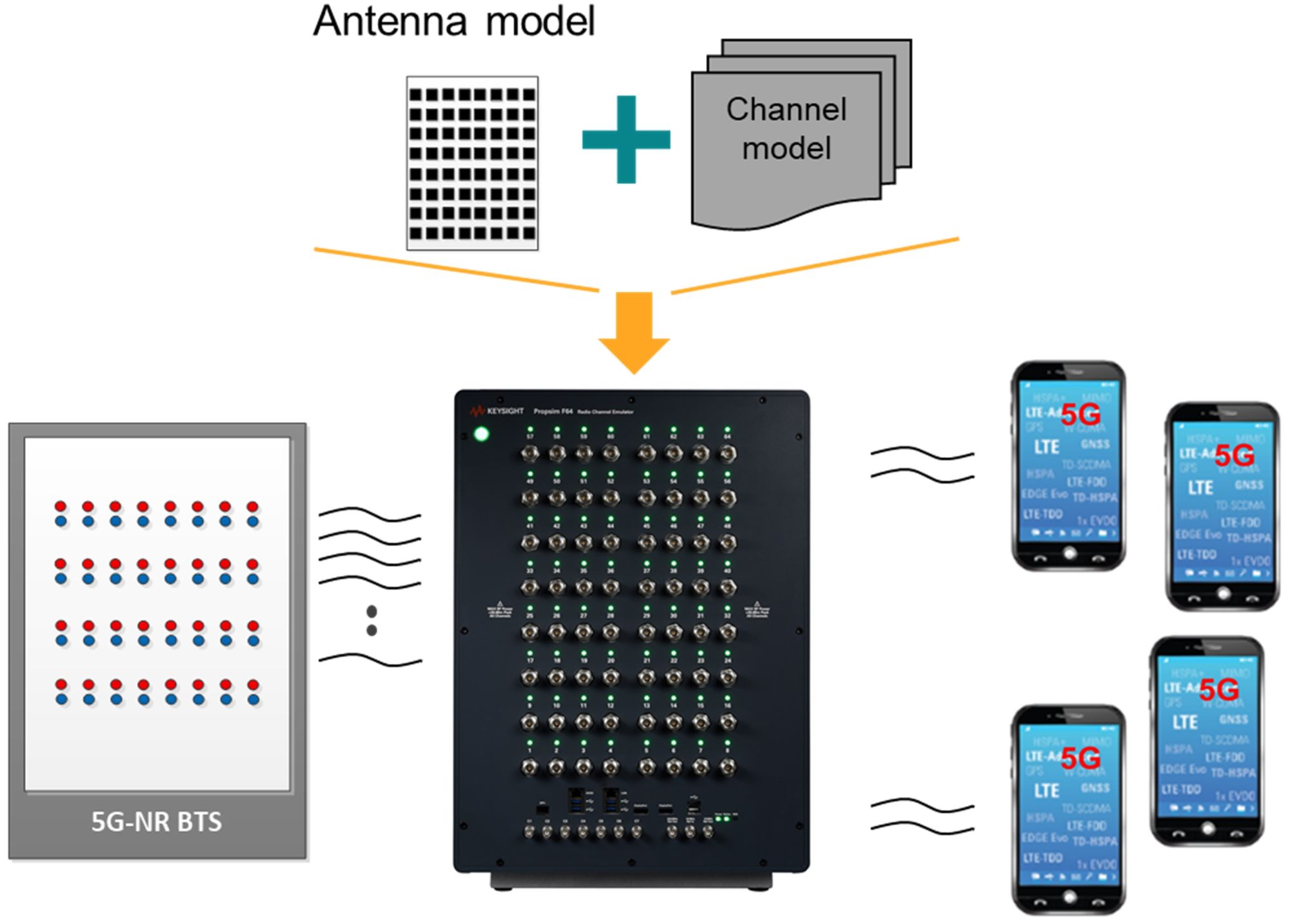
Figure 7. 5G massive MIMO test setup for FR1 uses a channel emulator that leverages antenna and channel models.
Simplified methods can also be implemented for specific applications. Base station full-array testing requires the full sampling of all RF lines from the base station and the UEs. To increase the capacity of the test environment and decrease the required amount of RF lines in the channel emulator, only parts of the lines can be sampled, leading to a simplified method for massive MIMO testing shown in Figure 8. Applications, such as radio access network (RAN) multi-cell testing and device massive MIMO IoT and performance testing, can use such an environment without any major drawbacks. In practice, the simplified environment features an antenna interface unit between the base station and the channel emulator to combine parts of the RF lines into a single line.
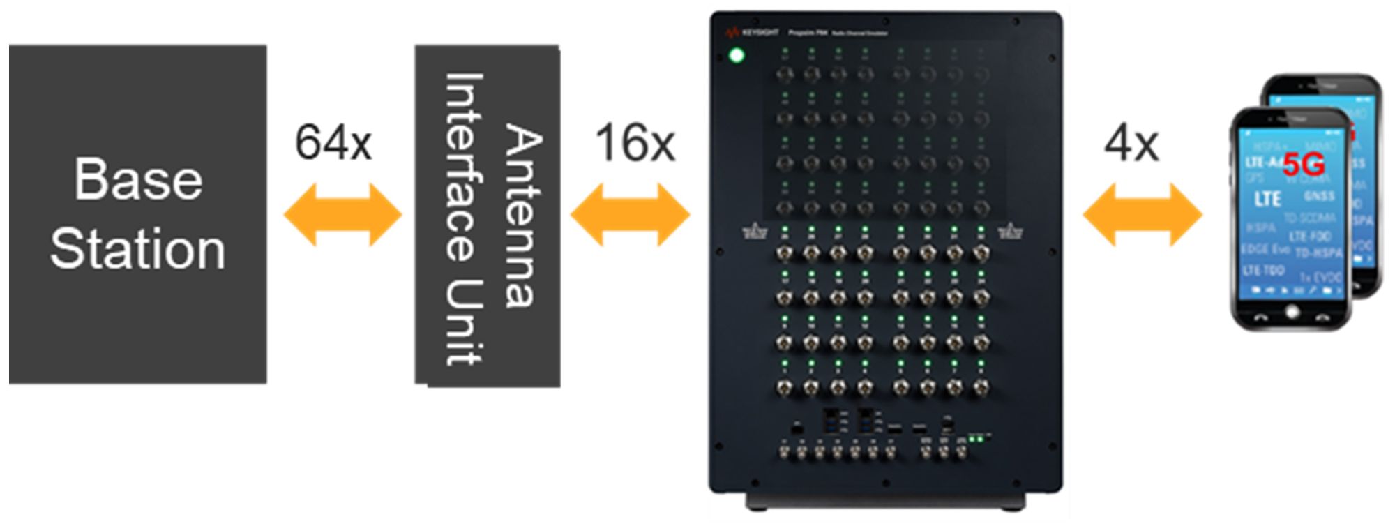
Figure 8. A simplified method for 5G MIMO FR1 testing increases test capacity.
For FR2 interoperability testing between the base station and the UEs, the test setup includes anechoic chambers for both ends (Figure 9). The channel emulator interconnects the chambers and all signal paths between the devices. In OTA testing, the channel emulator introduces the real-life propagation environment between the interconnected devices.
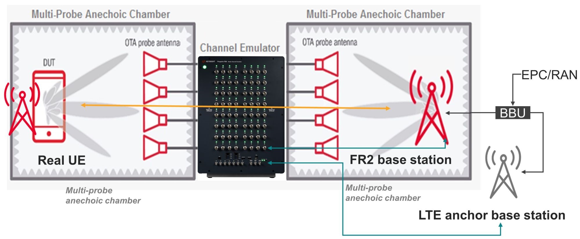
Figure 9. 5G mmWave end-to-end performance test setup where a channel emulator uses models to emulate real-life conditions such as signal degradation.
Successful 5G network deployments require performance testing with real-world conditions due to higher system complexity—notably from massive MIMO implementation. While 3GPP standards don’t provide all the required test scenarios for base station or UE massive MIMO performance testing, several new methods have emerged. Methods with channel emulators stand out by enabling realistic performance testing of 5G massive MIMO base stations and UEs while limiting the complexity of the test setups.
For more information on 5G channel emulation, visit Keysight Technologies’ 5G Solutions webpages:
 Jessy Cavazos joined Keysight’s Industry Solutions Marketing team in January 2019 with a focus on 5G. Prior to that, Jessy was the Industry Director for the Test & Measurement practice at Frost & Sullivan. She joined the global consulting and market research company in 2002 and tracked the Test & Measurement industry for more than 15 years. Jessy has authored numerous market studies highlighting key opportunities and disruptive trends and has been published in industry-leading publications. Jessy holds a bachelor’s degree in international business from the Institut de Formation Internationale located in Rouen, France, now part of the NEOMA Business Schools.


Tell Us What You Think!