Frequency synchronization in the radio access network (RAN) minimizes disturbances at the air interface, ensures mobile handover between radio base stations, and fulfills legal and regulatory requirements associated with a frequency license.
Radio-access networks (RANs) must minimize disturbances at the air interface. Disturbances in timing can upend synchronization of the radio RAN and ultimately to the downstream network. Strict timing requirements specified in industry standards ensure that base-station handovers occur smoothly and that a wireless network complies with legal and regulatory requirements associated with a frequency license.
Most legacy 2G, 3G, and 4G networks utilize frequency division duplex (FDD) where uplink and downlink radios transmit simultaneously but at different frequencies separated by some offset. This offset is an inefficient use of frequency spectrum, which is increasingly scarce and costly to acquire.
Time division duplex (TDD) offers a cost-effective alternative to expand access into unoccupied upper-spectrum ranges. In TDD mode, networks optimize spectral efficiency by sharing the same frequency for uplink and downlink radios, but at different times. Due to the time-sensitive nature in which networks send TDD data, phase (time) synchronization is required to meet tight frame-start specifications and avoid unwanted interference between neighboring base stations and user equipment.
Time synchronization also enables mainstream features and services to emerge in 5G networks. For example, carrier aggregation (CA) uses multiple radio frequencies to increase speed and reliability in challenging environments, enabling faster downloads and continuous video streaming. Multiple input multiple output (MIMO) technology combines multiple antennas at source and destination to provide a more stable connection with less congestion. Geolocation services let operators pinpoint the geographical location of devices connected to the Internet.
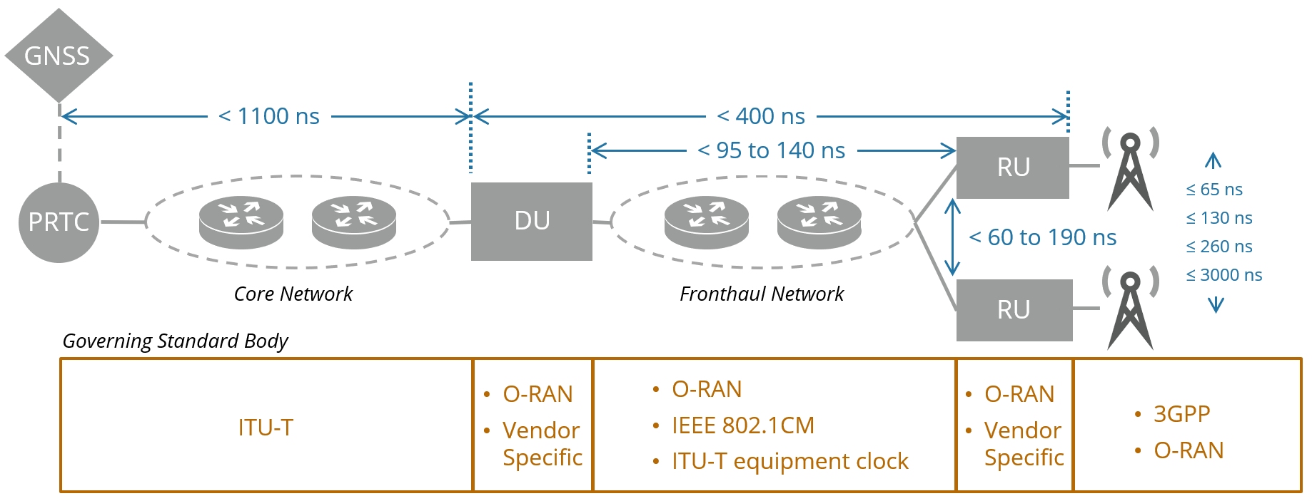
Figure 1. This example O-RAN C2 network shows an end-to-end time-error budget, enabling synchronization based on applicable standards. (Click image to enlarge.)
Timing requirements
Figure 1 shows an Open RAN, O-RAN network implementation illustrating how multiple standards combine to build an end-to-end solution enabling time synchronization. Here, time-error (TE) requirements appear budgeted throughout the network, measured with respect to a common reference. Overall, the total end-to-end TE must be less than ±1.5 μsec.
The ITU-T provides Recommendations to build the transport network, in which Question Group 13 from Working Party 3 in Study Group 15 addresses network synchronization and time distribution. Recommendation G.8271.1 specifies a maximum absolute network limit for TE of 1100 ns at reference point C, leaving 400 ns to the base station, as illustrated in Figure 1.
The O-RAN Fronthaul Working Group specification O-RAN.WG4.CUS.0-v07.00 assumes the fronthaul network has a maximum TE of 95 ns or 140 ns depending on whether a regular radio unit (O-RU) with device TE of 80 ns or enhanced O-RU (with device TE of 35 ns) is used. These TE limits are independent of the number of switches, two of which are shown in Fig. 1 for illustration only. The fronthaul network’s relative TE similarly varies between 60 nsec and 190 nsec, as shown in Fig. 1. Table 1 summarizes O-RAN time alignment error (TAE) requirements for various 5G features, where TAE measures the largest timing difference between any two signals.
| 5G Feature | Maximum |TAE| (normative) | Related 802.1cm/eCPRI Timing Category (informative) |
| TDD | 3 μsec | C |
| Dual Connectivity | 3 μsec | C |
| MIMO, TX Diversity | 65 nsec | – |
| CA (intraband contiguous per BS type) | 130 nsec | A |
| CA (intraband contiguous per BS type) | 260 nsec | B |
| CA (interband or intraband non-contiguous) | 3 μsec | C |
| Observed Time Difference Of Arrival (OTDOA), not defined by 3GPP | >> 1.5 μsec | – |
Table 1. O-RAN TAE Requirements for 5G Features per Table 9-2, O-RAN.WG4.CUS.0-v07.00.
Finally, 3GPP specifies RAN air interface requirements in TS 36.104, in which version 17.4.0 defines TAE to be less than 65 nsec, 130 nsec, 260 nsec and 260 nsec for MIMO at each carrier frequency, intra-band contiguous CA, intra-band non-contiguous CA, and inter-band carrier aggregation, respectively. 3GPP additionally specifies less than 50 ppb frequency error at the base-station air interface.
Other relevant standards enabling time synchronization include Synchronous Ethernet (SyncE), specified in ITU-T G.8262 and G.8262.1, which frequency synchronizes the Ethernet physical layer, and IEEE 1588 Precision Time Protocol (PTP), which enables clock synchronization in a computer network. Additionally, IEEE 802.1cm specifies time-sensitive networking for fronthaul streams in Ethernet, and an evolved common public radio interface (eCPRI) defines a protocol for remote radio units to communicate with base stations. Each of these standards plays a pivotal role in synchronizing 5G networks.
Synchronization and 5G timing challenges
One key trend emerging from the transition of 4G to 5G networks is densification. To increase capacity in metro areas with a high concentration of users, wireless carriers are deploying cellular radios all over the urban landscape. For example, radios will appear mounted on telephone poles, lamp posts, building corners, curbside municipal power-supply cabinets and below manhole covers. Such densification will subject these radios to a wide range of environmental stressors and require a higher level of performance from timing devices to ensure a reliable network. Let’s review a few common scenarios to understand their impact on timing.

Figure 2. A PTP servo loop locks a local clock to network time, filtering PDV in the process. (Click image to enlarge.)
Figure 2 illustrates a PTP servo loop, which is a fundamental building block for synchronizing time across distributed systems. The servo loop disciplines a local clock to network time, and in the process low-pass filters incoming network noise, known as packet-delay variation (PDV). Because filtering input noise is good, why not lower the loop bandwidth as much as possible? It turns out, because of where the local oscillator (LO) sits in the loop, as the loop bandwidth lowers, the LO noise that appears at the output increases. Eventually, this LO noise will dominate such that lowering the bandwidth further actually raises the total output noise. The optimum loop bandwidth is thus selected to balance incoming and internal noise processes. The key point is that selecting a lower-noise LO enables lowering the servo-loop bandwidth to filter more PDV, resulting in a more accurate local time (e.g. time stamps).
The bandwidth of the servo loop is such that the loop updates about once every few seconds. Between updates, the unfiltered local oscillator (LO) output frequency provides local time. Thus, the noise of the LO transfers to the local time between loop updates. This means the most important LO performance metric for synchronization applications is short-term stability. This is in contrast with traditional thinking, wherein precision oscillators are selected for their generic banner specification of “stability” (i.e. frequency-over-temperature stability), which is guaranteed over the lifetime of the product. Because the servo loop updates periodically, designers need not worry about longer time frames during locked operation (holdover being a separate consideration).

Figure 3. Synchronization applications depend on an oscillator’s ability to maintain constant output frequency in the presence of changing temperature. Here, curve 1 is a better choice, even though it’s rated lifetime stability is poorer. (Click image to enlarge.)
What is the dominant noise source in precision oscillators that contributes to short term instability? When operated in constant ambient temperature and airflow, random noise processes dominate. Allan deviation is one measure to quantify this noise. Otherwise, thermal stability can dominate. Referred to as dF/dT (the derivative of frequency versus temperature), thermal stability captures how an oscillator’s output frequency changes with changes in temperature. Figure 3 highlights the critical nature of dF/dT by comparing stability curves of two hypothetical devices. Device 1 has a poorer datasheet stability of ±100 ppb compared to ±50 ppb of Device 2. Because Device 1’s curve is smoother, it provides better (lower) peak dF/dT performance.
In the locked state, the system relies on the stability of the LO between PTP servo-loop updates to maintain a stable frequency in the presence of thermal gradients and dynamic airflow. Thus, what matters is an oscillator’s low sensitivity to temperature changes (dF/dT), not lifetime peak-to-peak stability. Additionally, smoother dF/dT performance enables easier thermal compensation, if desired.

Tell Us What You Think!