Embedded systems are trending toward greater complexity and higher levels of performance. A key means of optimizing embedded systems’ performance is improved frequency analysis, which test equipment makers are trying to address through new versions of their spectrum analyzers and oscilloscopes.
One such product is Tektronix’s recently introduced 6 Series Mixed Signal Oscilloscope (MSO). The scope’s enhanced capabilities and feature set enables embedded designers to provide efficient, timely, and accurate results in their research. Below are three of the biggest hurdles embedded designers have endured in recent years that devices like the 6 Series MSO are aiming to overcome.
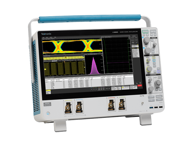
Devices like the 6 Series MSO from Tektronix are helping embedded designers overcome significant challenges with signal analysis (Image Credit: Tektronix)
1. Higher Performance
As layouts for embedded systems are getting smarter through incorporating more technologies like sensors, these designs are using faster clocks and high-speed serial buses for moving and processing larger volumes of data. To see these faster signals, embedded designers need higher performance capabilities from their equipment. One way vendors can meet these needs is extending the device’s performance threshold.
To aid designers working on faster, more complex embedded system formats, the 6 Series MSO, for example, has incorporated a frequency range spanning to 8 GHz, while simultaneously delivering a 25 GS/s sample rate on all four channels. According to Tektronix, this is an industry first for this oscilloscope class. The bolstered gigasamples per second rate on all channels enabled designers to accurately view up to four high-speed signals at once, while delivering a 16-bit resolution at 200 MHz when using the device’s High Res mode.
2. More Bandwidth, Less Noise
With the advances researchers and developers are beginning to utilize in spectrum analysis, they’re requiring more bandwidth and lower noise inputs. Sticking with the 6 Series MSO as an example, embedded designers can now improve measurement confidence with features like low-noise inputs, especially at the highest sensitivity settings, where this kind of assurance is most important.
Devices like the 6 Series MSO that are embracing and applying these new developmental advances in their designs, incorporate new low-noise preamplifier and application-specific integrated circuits (ASICs). These features significantly reduce noise, especially on signals in the hundreds of millivolts peak-to-peak.
3. New Power Requirements
Keeping ASICs on topic, designers are starting to ensure clean power to these complex systems (along with field-programmable gate arrays—FPGAs), leading to new power technologies and mandates. With this next wave of devices that the 6 Series MSO represents, these conditions will allow designers to measure aspects like DC power rails with improved accuracy and resolution, while reducing the time needed to understand high frequency in a design’s power rails. As a result, designers can see interfering signals on power rails, and measure them with a high level of accuracy.
To aid embedded designers, the 6 Series features a built-in arbitrary/function generator, free DVM, along with trigger frequency counter containing product registration, protocol options, and even a choice of operating systems. The 6 Series can also undergo bandwidth promotions (starting at 1 GHz) that extend up to 8 GHz, which is another capability signal analyzers will start to possess and only require a simple license upgrade.