Waveform amplifier is a new kind of equipment and it is valuable piece of bench test equipment to have in the lab. Most function generators or signal generators output voltages are limited to about +/-5V into a 50 ohm load. Such generators output impedance is typically 50 ohm, making them unsuitable for driving low resistance (high-current) loads. For applications require higher current or higher voltage or higher power, a waveform amplifier is required. It is ideal for function generator amplifier.
Understand Function Generator Limitations
Waveform generators such as those of function generator, arbitrary waveform generator, and signal generator, output 5V into a 50-ohm load. If the load impedance is lower, its output voltage is further lowered. These function generator output current is about 100mA. Figure 1 shows a simplify circuit for a function/signal generator output. These generators are designed for 50 ohm signaling and termination. The connection between coaxial cable and load should be 50 ohm so that the signals are terminated properly without reflection. The 50 ohm source impedance severely limits its output voltage and current. In general it is not recommended for generators to drive any load less than 50 ohm. For higher voltage or current, or the load impedance is lower than 50 ohm, a function generator amplifier is needed.
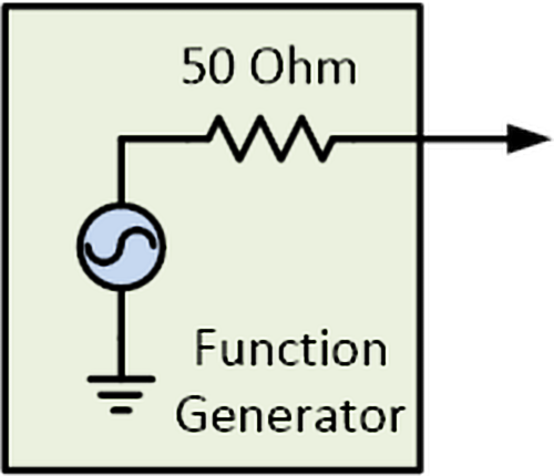
Figure 1. Diagram showing function generator internal 50 ohm source resistance.
Waveform Distortion
To further illustrate the short comings of signal generator’s 50 ohm source impedance consider the below cases. When driving heavy loads or low impedance, the function generator’s high output impedance will greatly distort the signal or waveform. Figure 2 to Figure 4 depicts the signal distortion and attenuation effects. A waveform generator produces a square-wave, but the waveform is distorted by the load (resistor, capacitor, or inductor). As shown in Figure 2, the 50 ohm output impedance and the 5-ohm resistor load form a voltage divider that attenuates the voltage signal by 11 times. If the load is capacitor, the signal generator’s output impedance and the load capacitance formed a low-pass RC filter. The RC filter distorts output waveforms as shown in Figure 3. Waveform generator with 50 ohm source impedance also reduces the maximum frequency for capacitive load. Function generators in generally cannot drive large capacitive load. In a similar manor, inductive loads such as relays or electromagnetic coils, the signal is also distorted as shown in Figure 4. To overcome these distortions, the function generator must amplify or “buffered” with a driver whose source impedance is very low (i.e. 50mOhm) and able to output enough current (i.e. up to 6A).

Figure 2. The 50 ohm output impedance attenuates the signal.

Figure 3. Function generator’s 50 ohm source impedance distorts the signal with capacitive load by causing the slow rising edge.

Figure 4. Signal is distorted by the combine of inductive load and the signal generator’s 50 ohm output impedance.
Driving High-Voltage Devices
Many test and measurement applications require higher voltage than that of a function generator can provide. Example of these are piezoelectric transducers (10V to 150V or more), electromechanical relays (>28V), power supplies noise (>48V), and much more. Since most voltage signal from generators can only outputs about 5V or less. A voltage amplifier is needed to boost the voltage. As shown in Figure 5, the amplifier combined with a function generator is acting like a high-voltage function generator. It amplifies the function generator’s low voltage output to higher voltages. Typical such amplifier have gain of 20dB (gain factor of 10V/V), some has higher gain factor of 50 for higher output voltage (>50V).

Figure 5. Combine two equipment forms a high voltage function generator driving a high voltage piezo transducer.
High-Current Load
In some applications, the load or DUT (device-under-test) requires high current, but not necessary high voltage. Such applications include driving high current through a magnetic coil to produce high magnetic field for scientific experiments. In this case voltage is not important. In some other cases, both high current and high voltage are required. Such examples include power supply voltage transient test and pulse thermal transient responds. Most laboratory signal generator or signal source can neither produce high current nor high voltage. A general purpose laboratory grade function generator amplifier is capable of sourcing high current and high voltage is needed for many of these applications. An example is shown in Figure 6 where the amplifier is driving a motor using PWM signal to control the speed. The motor requires both high current and high voltage.

Figure 6. Waveform amplifier is ideal for testing PWM motor.
Weak Signal Sources
Besides function generators, there are other test signal sources that are very weak. Example of such weak signal source is DAQ (data acquisition system) outputs. Unlike waveform generator whose output impedance is 50 Ohm, DAQ output impedance is generally low-impedance in the order of 1 Ohm or so, but their driving strength is weak typically 1mA, compared to signal generator can drive up to 100mA. These DAQ analog outputs typically expect to see a load of 1k ohm or more. In many laboratory test applications, the devices under test (DUT) or load is much lower than 1k Ohm. Example of these low-ohmic resistance DUT are Helmholtz coils (~50m ohm), solenoid valves, thermal heating elements, etc. To drive these low-ohmic DUTs, a high-current waveform amplifier is needed as shown in Figure 7.

Figure 7. Waveform amplifier is great for buffering DAQ to output high current for driving coil.
Laboratory Waveform Amplifier
The previous sections discussed a number of lab bench test and measurement applications where lab amplifier is needed. Several example cases how an amplifier driver overcomes many limitations of function generator. Let’s pick the TS250 Waveform Amplifier as an example to discuss the required features. The TS250 and its functional equivalent diagram is shown in Figure 8 and 9.
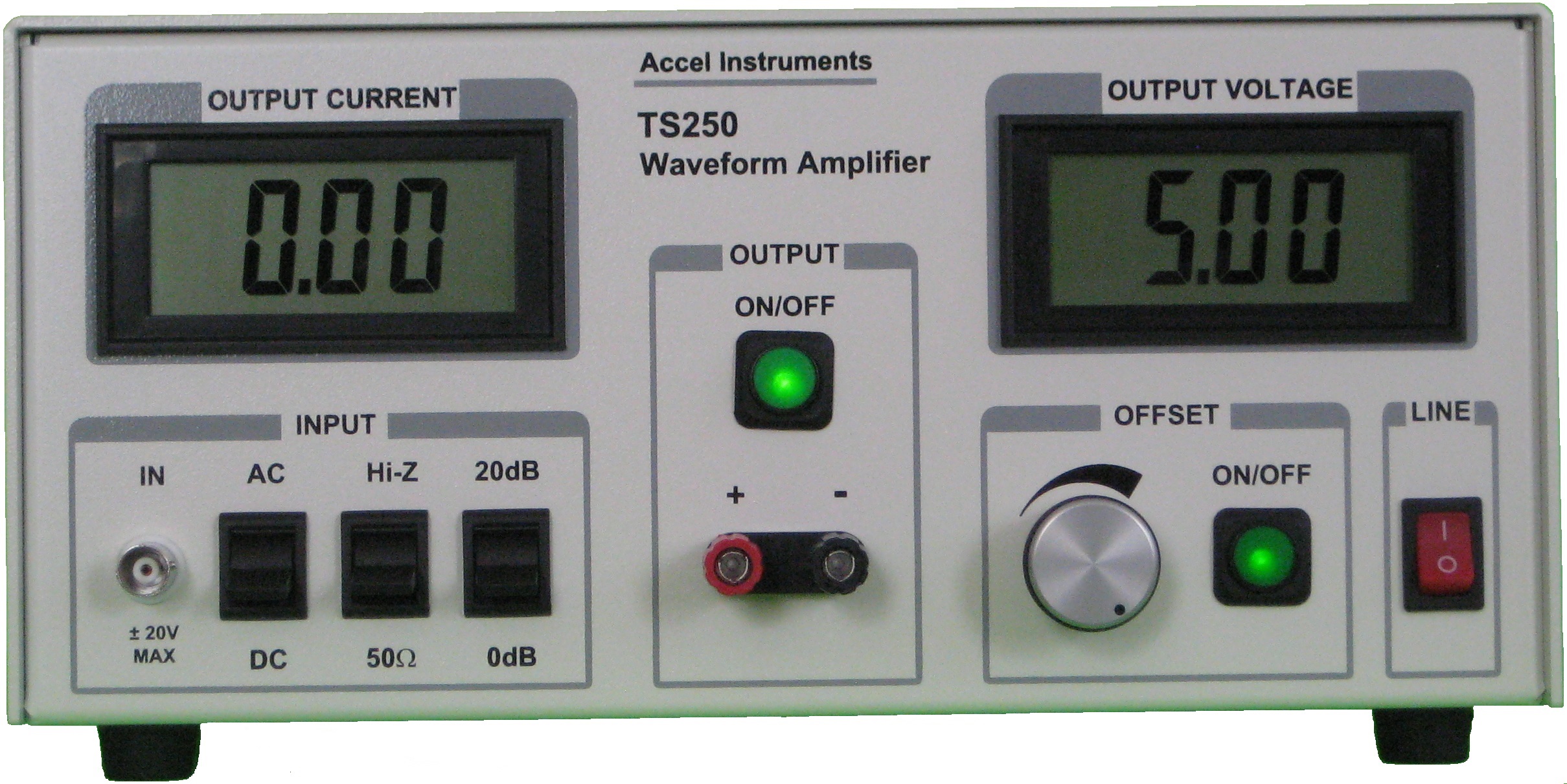
Figure 8. TS250 Waveform Amplifier for laboratory testing.

Figure 9. A simplify functional equivalent diagram of a bench waveform amplifier.
Boost Voltage
For test cases where high voltage is needed (>10V), the waveform amplifier must able to amplifier the voltage input voltage. Consider most signal generators and DAQs output is +/-5V, the amplifier must have enough gain to output the maximum specified voltage. Typically a gain factor of 10V/V (20dB) is sufficient. If the lab amp output is in the range of 100V, a gain factor of 50V/V is needed. Some function generator amplifier event offer variable gain.
Buffer for High Output Current
Some measurement cases where the voltage gain is not needed, but required high output current (i.e. 3V and 6A). The signal generator amplifier needs a unity gain (gain of 1V/V) setting. For these test cases, the amplifier must able to output high current. Furthermore, the waveform amplifier output impedance (resistive + inductive) should be small (i.e. 50mOhm + 50nH typical or less). See Figure 8 for details.
Input Impedance
Most bench top waveform generators have output impedance of 50 ohm. The 50 ohm source impedance is needed for working with 50 ohm cable to maintain good signal integrity by terminating the signal. The 50 ohm signal system is important for high frequency or high slew-rate signals, because proper termination reduces or eliminates reflection. Therefore a laboratory waveform amplifier should feature a 50 ohm input impedance. So the function generator output connecting to the waveform amplifier input (Figure 5) using a 50 ohm coaxial cable to maintain signal integrity.
On the other hand, most DAQ system analog output cannot drive a 50 ohm load. These analog outputs can drive 1k ohm or higher (Figure 6). Therefore the bench waveform amplifier needs to have a high impedance input mode as well as a 50 ohm mode. The user may select the input impedance that is best match their signal source.
Input Coupling
To accommodate variable of signal source and test scenarios, two additional features are good to have. The first feature is input coupling. A selectable AC-coupled or DC-coupled input is useful. While most use cases are DC-coupled, AC-coupled input may be used for the case where the AC signal is to be amplify, while blocking the DC signal.
DC Offset
Another good feature is the DC offset. This feature mimics a function generator’s DC offset setting. This function is good for test cases that requires a DC voltage output as well as an AC signal. Another example is simply using the waveform amplifier as a four-quadrant power supply by using the DC offset to control the voltage.

