The traditional key requirements for RF power measurements for wireless chipset or power amplifier manufacturing are good repeatability, fast measurement speed, and high accuracy. An emerging requirement is becoming increasingly important: obtaining a wide power measurement range, especially on the lower power level. This new requirement is due to the emergence of chipsets designed to handle a wider power range in order to support higher data throughput and wider coverage area.
Typical Test Setup
Figure 1 shows the typical test setup for wireless chipset manufacturing test. Three power sensors are used to measure the chipset’s input power, output power, and reflected power. A spectrum analyzer is used to measure other critical parameters such as ACPR, EVM, and harmonics. Care should be taken to ensure that the power to be measured does not exceed the sensor’s measurable power range in order to avoid damaging the sensor, particularly at the power amplifier’s output.
Depending on the signal formats, a trigger output signal from the signal source can be connected to the trigger input ports of the power sensors in order to synchronize the signal burst timing and sensors’ measurement acquisitions.
Figure 1: Typical test setup for wireless chipset manufacturing test
Average Mode Time-Selectivity Measurements
Conventional average power sensors only offer waveform average power measurements without the ability to control which portion of the waveform to be captured. For a pulsed signal, only the average power of the pulsed waveform will be obtained, which averages the off and on period. With advances in FPGA processing and breakthroughs in signal conditioning architecture, there is now precise control on which portion of the waveform is to be measured, even with an average power sensor.
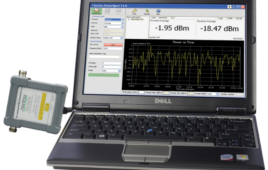
The hardware settling time is extremely fast, allowing high speed and real-time measurements without missing any signal details. The Keysight U2040 X-Series wide dynamic range power sensors are one such example.
A U2040 X-Series sensor accepts external trigger input TTL signal to control the start of the measurement acquisition. Users can then set up the aperture duration to match the length of the signal. For instance, for LTE-TDD measurements, an external trigger signal can be used to synchronize the start of the sensor’s acquisition with the rising edge of the LTE burst, and the sensor’s aperture can be set up to 1 ms to match the length of the burst.
With this configuration, you can now measure only the burst and ignore the rest of the off region (refer to figure 2). This is a function known as average mode time-selectivity, and offers similar results as the time-gated average power measurements offered by peak sensors, which are often more expensive.
If there is no external trigger signal to synchronize the sensor’s acquisition with the burst timing, users can use free run average power measurements with the duty cycle method to perform burst or pulse power measurements.
Simply set the aperture duration to match the signal period and input the duty cycle of the signal for the sensor to automatically calculate the pulse power (pulse power = average power/duty cycle). The sensor can then perform very fast and accurate pulse power measurement without needing a large average count setting as required by conventional sensors.
Figure 2: Measurement of an LTE burst using the average mode time-selectivity method
Achieving Measurements over a Wide Dynamic Range
Another key advantage with the average mode time-selectivity method is the wide power range that is available in average power sensors. If the power sensors in the market today can be scanned, it is easy to notice a trend – an average sensor always offers a wider power range (80 dB or more) compared to a peak sensor (50 dB). This is due to a typical diode detector in an average sensor’s design, which will convert the input RF signal to voltage in nano-volt.
Such small voltage will require amplification to yield a level that can be accurately processed by the ADC. However, these amplifiers do not work well in DC. Chopper circuits are commonly used in average power sensors to improve the amplifier’s performance by removing 1/f noise (or flicker noise). This method yields a wider power range in average power sensors by reducing the amplifier’s noise. This method is not suitable for peak power sensors, however, meaning these sensors will have a narrower dynamic range compared to average sensors.
With average mode time-selectivity, the benefits of both worlds can be enjoyed – the precise timing control of a peak sensor, and the wide power range of an average sensor. This new function is especially useful for wireless chipset manufacturing, where average or time-gated average power measurements are frequently performed over a wide power range and require extremely fast speed. A wide dynamic range power sensor will always provide fast measurement speed as no averaging is required when measuring low power signals. The same sensor for test system calibration over a much wider range can also be reused.
Time-Gated Power Measurements
In some wireless applications, such as wireless module or board level testing, it is not possible to derive an external trigger signal from the device-under-test (DUT) or signal generator. Therefore it is the power sensor that must support internal trigger function. Using the internal trigger function, the DUT output signal level is compared against the internal trigger level setting in the sensor in order to qualify for a valid trigger.
The average mode time-selectivity function only supports immediate and external trigger for measurement timing control. For an application where the external trigger signal is not available and timing control of the measurement is important, users will have to fall on the conventional time-gated measurement offered by a peak sensor. In this mode, the trigger source can be set to immediate, internal, or external.
The good news is that modern power sensors such as the Keysight U2040 X-Series are able to support both average mode time-selectivity and time-gated power measurements, offering the flexibility of configuring the sensor into different modes based on your measurement needs.
Figure 3: Measurement of an LTE burst using internal trigger time-gated power measurements
Advance List Mode
Most wireless chipsets are designed to operate over multiple modes or support multiple signal formats. It is therefore important to test all of the formats supported by the chipsets to ensure that they are meeting performance specifications, but testing all the supported formats results in long test times.
Having the capability to pre-define a list of measurements based on the different formats will come in handy. For instance, a chipset that supports 2G, 3G, and 4G cellular formats will need to be tested for GSM, WCDMA, LTE, and other signal formats at different power levels. The sensor can be set up to measure 900 MHz GSM signals at high, medium, and low powers for the first three acquisitions, measure 1,900 MHz WCDMA signals for the three subsequent acquisitions, and measure 700 MHz LTE signals for the subsequent acquisitions (refer to figure 4).
Timing synchronization between the sensor and the DUT/source is achieved through a hardware handshake with the power sensor’s built-in trigger in and trigger out ports. With every trigger input signal received, the sensor performs measurement capture base on the predefined settings and saves the measurement in its buffer memory, and then generate a trigger output to signal the advancement to next step. Once the whole sequence is completed, you can perform one fetch to retrieve all the measurements. This reduces programming overhead and idle times in the setup of the sensor or DUT/source.
The Keysight U2040 X-Series features an advance list mode to expedite this type of testing.
Figure 4: Speed up the measurements of multiple format signals with advance list mode
The explosive growth of mobile communications and higher data rates increase the complexity of chipsets, which need to support wider bandwidths and more cellular standards. Engineers who test these wireless chipsets are driven to constantly look for solutions to lower cost of test and increase throughput and test coverage while ensuring that the chipsets meet required performance levels.
Advances in RF power sensors play an important role in achieving that by offering a wider dynamic range, faster measurement speed and lower cost. The Keysight U2040 X-Series is the ideal solution to meet these needs. The U2040 X-Series comes with the world’s widest dynamic range found in a power sensor (-70 dB to +26 dBm) and the breakthrough average mode time-selectivity function, which enables extremely fast measurement speed for average and time-gated average power measurements.
For more information about how to achieve fast and accurate power measurements over a wide dynamic range for wireless chipset manufacturing, please refer to the application note at www.keysight.com/find/rfpowertips.
*Keysight Technologies Inc., formerly Agilent Technologies electronic measurement business


