A quarter or more of the spectrum-time resource in a cellular network is used for channel operation and control for functions like sounding, providing state information, equalizing, and tracking. An understanding of the radio channel that suits the spectrum, antenna design, and user application is therefore fundamental to the design of an effective radio system. When the system has to use transmitters and receivers from many different vendors, like in the case with 5G, the channel model and applications have to agree before waveform and device design can begin.
This article describes what is needed to understand and model channels, particularly those above 6 GHz. As the carrier frequency increases, so does the need for directional antennas to overcome path loss and the sensitivity of the channel response to movement. The lamp post scenario in figure 1 is a good example of the problem. In the same way a mismatched signal on a cable is reflected and causes frequency-dependent ripple in the S21 response, multiple paths in the radio channel create a frequency-dependent response the receiver has to equalize and track. Unlike a cable, the length of two or more paths in the channel can and will change. As indicated in figure 1, the carrier frequency where they cancel each other out will move. Either the transmission has to be finished before it moves too much or the receiver has to track the changes. It’s important to understand these effects to confirm the channel model represents what happens in reality.
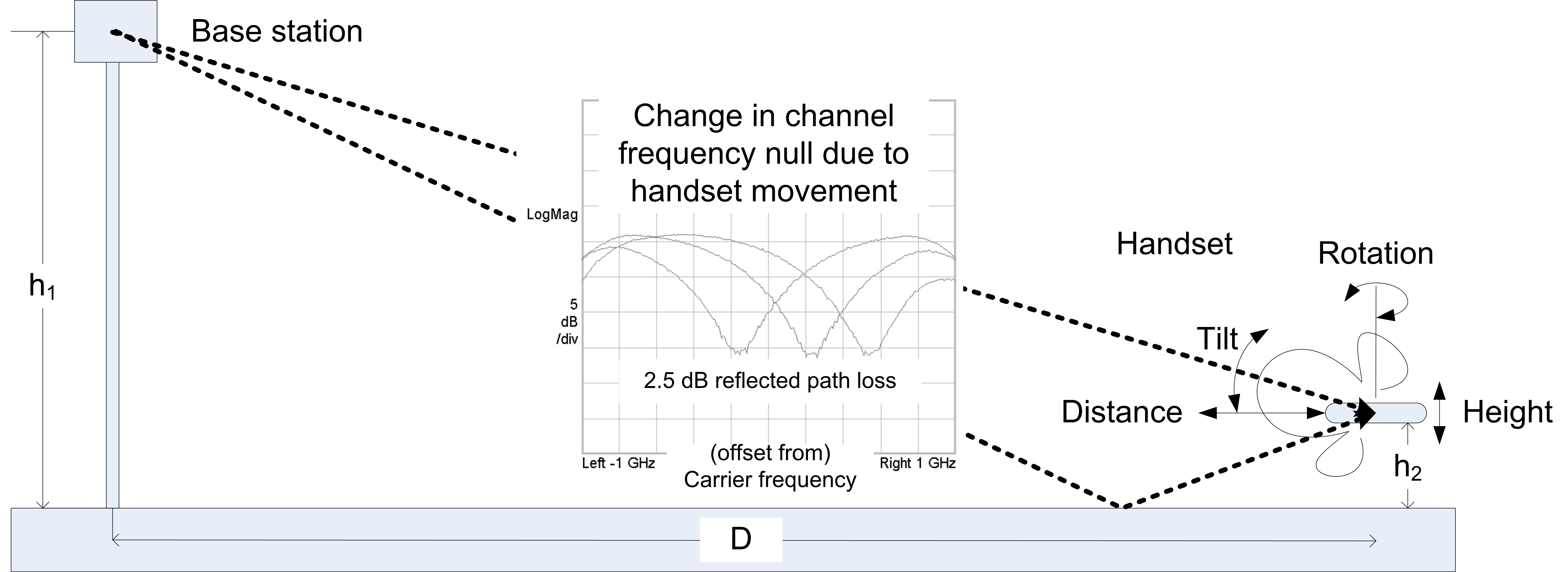
Figure 1: The lamp post scenario illustrating the problem of a radio channel with moving signal paths.
We start with a comparison of the three-channel sounding measurement methods being employed today before focusing on a “real-time” technique that enables time dependent and multi-channel analysis. This provides the closest match to the kind of signals likely to be employed in physical radios. In the example described, there is also a direct connection between the initial channel modelling and device design and measurement.
The Channel Model
Much work has been done to develop channel models for cellular radio below 6 GHz. Analysis of impairments affecting fixed point-to-point systems at cm and mm wavelengths is also available, as is an indoor model for IEEE 802.11ad operating at 60 GHz. The use of cm or mmWave as a cellular radio access technology is new territory.
As shown in figure 2, physical measurements are only one contribution to a channel model. Ray tracing is taking over from noise-based methods. An adaptation of the WINNER II model appears to be a favored outcome for 5G. With a stronger focus on higher throughput rates and shorter range, IEEE 802.11ay may take a different approach.
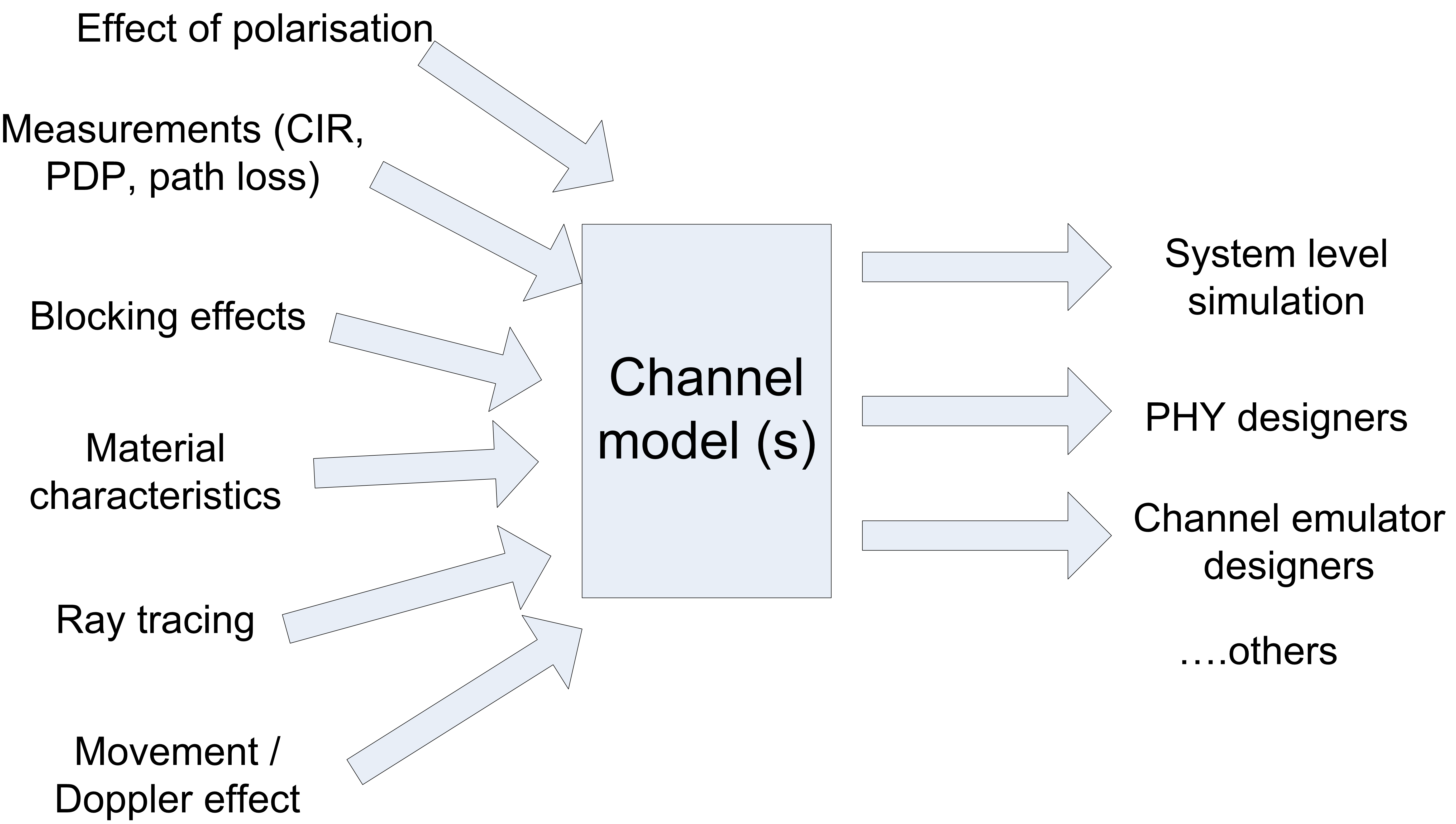
Figure 2: Inputs to the channel model and users of the channel model.
Measurement Methods
From high gain, narrow beamwidth horns to wide beam dipoles or various types of array, the choice of antenna has to consider the expected signal path loss, the parameters to be extracted, and the measurement method. Three types of measurement are in common use: the sliding correlator, swept CW (Vector Network Analyzer), and wideband modulated signal transmission and recovery. The benefits and constraints are summarized in table 1. All three methods require precision timing alignment to recover absolute path delay. However, using a wideband receiver that can synchronize to a known coded signal enables relative path measurements without triggering.
As far as measurements are concerned, the time interval and dynamic range of the measurement responses are the main distinguishing features. If the measurement interval is longer than the channel coherence time, movement in the channel cannot be isolated and will introduce uncertainty into the result. The dynamic range of the CIR measurement has to be high enough to isolate significant paths in the channel (e.g. those within a 20 dB range) and with enough margin to extract movement effects. Although not discussed in this article, calibration of any method is needed to ensure the measurement is sufficiently accurate. Validation is needed to understand the limitations due to measurement architecture and uncover any unexpected implementation issues.
Sliding Correlator
A BPSK signal, typically a PN sequence with a clock frequency the same as the test bandwidth, is modulated onto the RF carrier. At the receiver, the same sequence, running at a slightly offset clock frequency, is mixed with the recovered signal. The method can be thought of as being something like a digital version of a sampling oscilloscope. The transmitter and receiver front end need to have the full instantaneous bandwidth of the desired sounding measurement. The down-converted signal and DSP does not need such a wide bandwidth. Like a sampling oscilloscope, if the signal from the device-under-test (i.e. the channel) is sufficiently stable over time, a result equivalent to measuring using the full signal bandwidth can be built up over time.
Swept CW
A CW signal is swept over the test bandwidth at a rate dependent on the capability of the hardware design. A 0 dB peak/average eases the transmitter hardware design. The tuned frequency of a narrow band receiver tracks the transmitter. In a normal vector network analyzer, the source and receiver are in the same place and share the swept local oscillator, so synchronization is inherent. In the case of a channel sounder, the receiver is remote from the source, so care is needed to make this possible. In some cases, fiber optic cables are used to allow remote siting of the receiver. An alternative, which doesn’t require any cable connections between source and receiver, is to use precision swept signal generation using DDS.
Wideband Correlated Signal Transmission and Capture
This type of system provides a function equivalent to a vector network analyzer but enables very short measurement intervals and does not need cable interconnection. If the absolute path delay is not required, no special measures are required to maintain timing or frequency alignment between source and receiver.
While the sliding correlator transmits a “spread spectrum” signal, the design of that signal is constrained to suit the needs of the receiver. More generally, a wideband, very short duration test signal can be designed with a low peak/average power ratio to ease hardware linearity requirements. Short measurement intervals enable multiplexing of signal transmission within the channel coherence time.
Choosing a coded signal with good autocorrelation properties allows significant coding gain and vector averaging, resulting in a flexible trade-off with measurement interval to improve the measurement dynamic range.
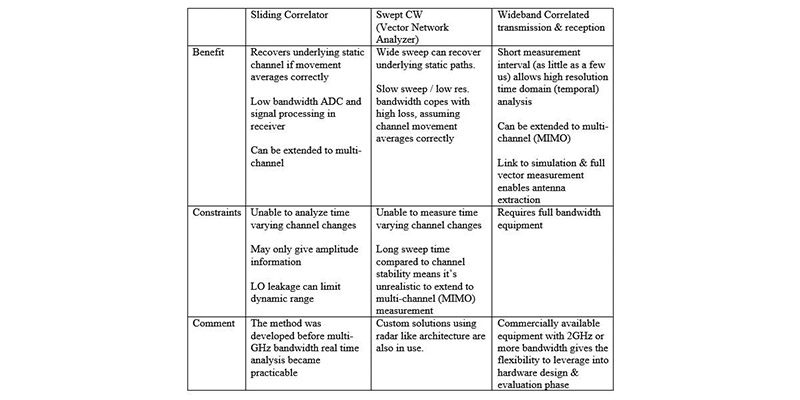
Table 1: Benefits and constraints of channel measurement methods.
Analyzing the Channel Response
The channel impulse response, CIR, is the main measurement of interest. It has to be qualified with information about the antenna to be useful. A subsidiary calculation is the power delay profile, PDP. This gives an indication of how complex the multipath environment is and potentially how difficult the signal will be for a receiver to demodulate. Channel movement and the signal to interference and noise ratio have to be assessed for a complete picture.
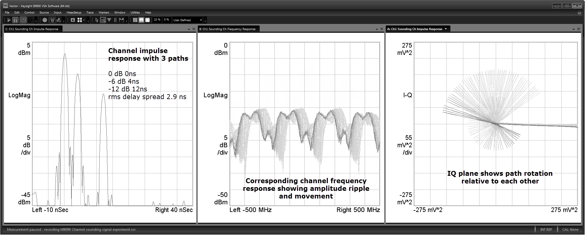
Figure 3: Movement in the channel measurement may not be apparent in the power delay profile (left), but the channel frequency response does show the variation. The rotation of the paths is also visible in the vector (IQ) trace on the right.
Extension to Multiple Channels
There are a number of reasons to make measurements with more than one input and output. The need for directional antennas at mm wavelengths means there are new channel characteristics affecting both basic signal discovery prior to beam steering and the use of MIMO. Angle of Arrival and Angle of Departure measurements may be made using rotating platforms if the underlying channel is sufficiently stable, but not the cross path response of MIMO. Paths associated with transient effects will not be seen. Polarization is one way a channel may support MIMO operation and can be treated in the same way. Figure 4 shows the configuration of a wideband system that is effective for multi-channel measurements.
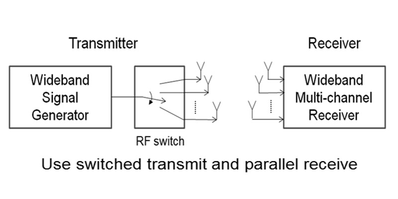
Figure 4: Multiplexing at the transmitter with parallel receivers gives a practical measurement configuration with a wideband system.
Office Measurement Example
The variation in channel response as a path reflector is rotated and is clearly seen in figure 5. The interaction with other reflections when using open waveguide antennas is complex, even over a distance of a few meters.
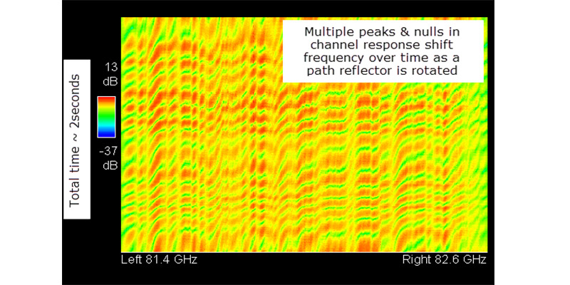
Figure 5: Variations in channel response due to a path reflector rotating 45 degrees in 2 seconds, causing 360 degrees of carrier rotation every 80 ms.
Summary
Measurement of mm channels gives important insights into the effects practical radio systems will need to work with. They will also be used to build up the channel models needed by the 5G industry to design new signal types with the antenna systems and radios to implement them. This article has shown how different channel-sounding systems can contribute to an improved knowledge of the mmWave channel, and more specifically, how methods based on commercially available equipment can provide some of the deepest insights into channel behavior.