It is no mystery that the Internet of Things (IoT) is geared to proliferate in the coming decades. With the number of short-range IoT gadgets predicted to surpass mobile devices, IoT will permeate industrial, commercial, and consumer applications. That being said, the landscape of IoT end devices, gateways, modems, and base stations is fraught with many standards organizations with respective protocols attempting to mitigate the limitations that come with custom proprietary hardware and a lack of vendor neutrality. These consortiums also attempt to optimize the hardware and software specifications for a particular application, so that (while there is no one-size-fits-all IoT platform) there is likely a standard physical (PHY) and medium access control (MAC) layer that would best fit an application of choice. For instance, the WirelessHART standard was developed by the HART communication foundation with low latency, high reliability, decent battery life (3-5 years) and medium throughput (~150 Mbps) transmissions for the Industrial IoT (IIoT). The up-and-coming Low Power Wide Area Network (LPWAN) architectures allow for ultra-high link distances (<1 km), extremely high battery lifetimes (~10 years), and low throughput on the order of bit per second (bps) transmissions for agricultural, industrial, medical, and smart city applications.
Along with this diverse ecosystem of IoT alliances come a myriad of end-devices utilizing all sorts of sensors/actuators, MEMS devices, batteries/cells, energy harvest techniques, radio modules, and finally, antennas. In any wireless application the choice and design of the antenna varies depending on the space available, transmission strength, and frequency range. Still, there are significant differences between the various wireless network topologies out there.
Different Antenna Needs for Low Bandwidth Applications
IoT is unlike extremely high throughput wireless networks such as 5G, high-efficiency wireless (HEW also known as IEEE 802.11ax), and WiGig that boost speeds on the order of 10 Gbps through utilization vast continuous spectrum space in the millimeter-wave (mmWave) bands or through the use of high order advanced modulation schemes such as carrier aggregation, 64-QAM OFDM and multi-user multiple-input and multiple-output (MU-MIMO). Networks such as these will often use highly sophisticated antenna structures like Active Electronically Scanning Antennas (AESAs) such as phased array antennas or switched beam arrays in Massive MIMO and microcell installations.
IoT networks and devices instead, leverage the licensed and unlicensed sub-6 GHz bands using tiny amounts of bandwidth (<5 MHz) whereas LTE-A uses up to 20 MHz with carrier aggregation and beyond that with mmWave spectrum utilization for 5G. Instead of leveraging beamforming algorithms with AESAs, IoT networks use star, mesh, or point-to-point topologies to smartly guide uplinks and downlinks between gateways and end-devices. Oftentimes, this means the job of establishing a link is accomplished through the use of relatively simple omni-directional antenna structures such as chip, PCB, whip, rubber duck, patch, and wire antennas. Many IoT-based development kits and radio modules such as Qualcomm’s Internet-of-Everything (IoE) development platform or the Arduino GSM come with GPS, Bluetooth, and WiFi antennas.

Figure 1: IoT devices rely on specific topologies—often either star or mesh—to relay data from node-to-node or from gateway-to-node. The ideal network structure depends upon the required link distance (mesh topologies are limited to very short distances), battery usage (mesh must always be on standby while star-based devices can go into sleep modes), and latency (depending up on the number of hops from nodes to get to the cloud). (Image Credit: Fujitsu)
Antennas Parameters
There are generally two defining parameters for antennas: gain and directivity. Directivity expresses the concentration of a beam radiation in a particular direction. Omni-directional antennas are, therefore, somewhat evenly concentrated in all three dimensions, while a directional antenna exhibits narrower radiation patterns. This is often accomplished by combining multiple radiating elements. Gain—a specification most often seen on datasheets—is a measurement of the total power radiated from an antenna.
IoT networks that utilize the unlicensed ISM bands must be within the Equivalent (or Effective) Isotropic Radiated Power (EIRP) required, as specified by the FCC in order to be a licensed digital transmitter, mitigating the risk of any interference on congested spectrum space. The EIRP is the total power an ideal isotropic antenna would have to put out to provide the same signal strength as the Antenna Under Test (AUT) in the direction of the AUT’s strongest beam. This parameter takes into account the gain, transmitter output power, as well as the loss due to the antenna feed and therefore provides a more holistic perspective of the transceiver module.
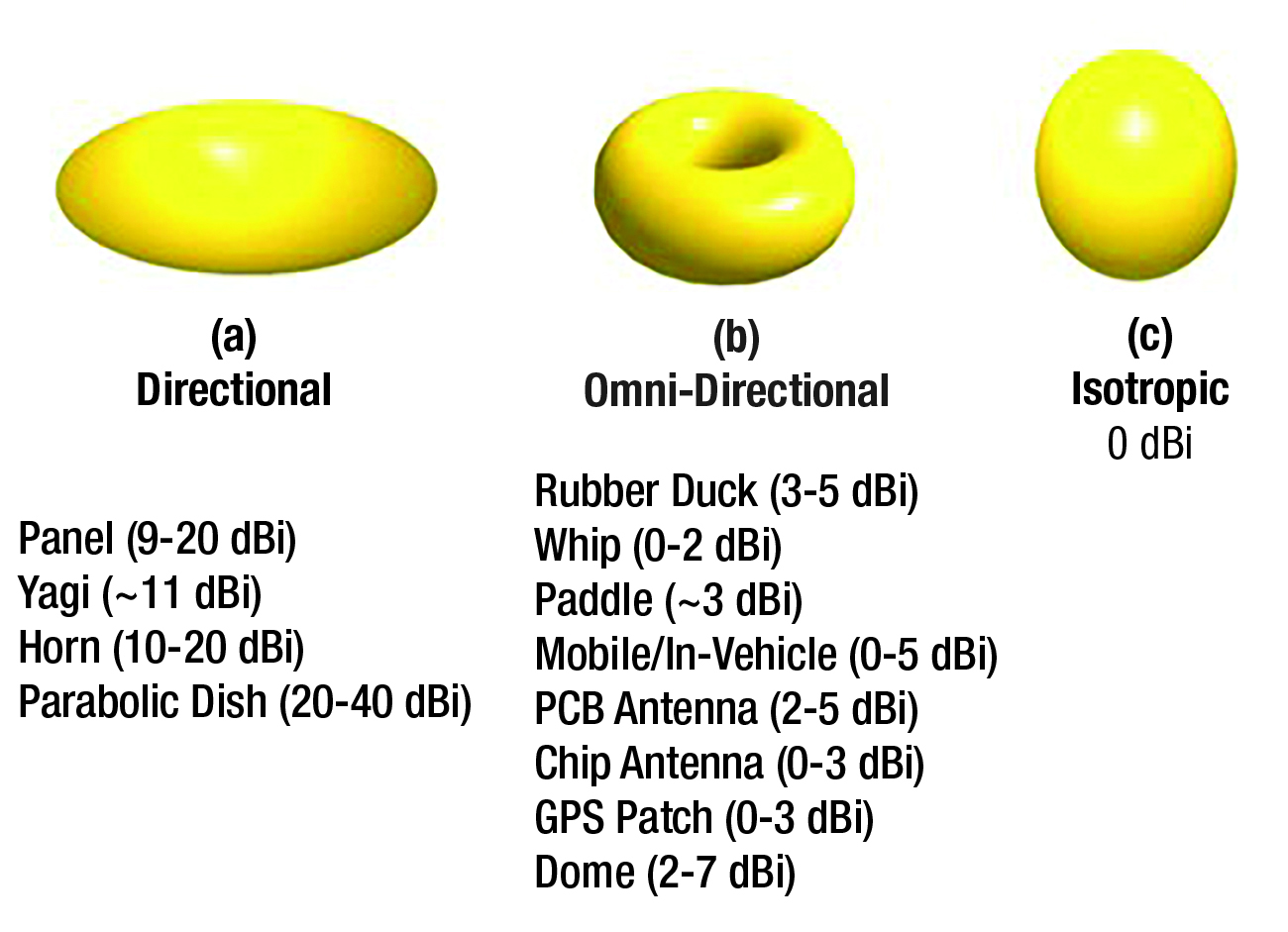
Figure 2: Antennas can present either directional or omni-directional radiation patterns. These patterns vary depending on the antenna type.
Antennas Used in IoT Devices
The typical antenna leveraged in IoT end-devices are listed above: wire, whip, rubber duck, paddle, chip, and PCB. There are variants with dual/multi-band antennas and flexible antenna structures for applications that require the antenna be routed along the body of the device (e.g.: UAV). As stated earlier, the frequency of the given IoT application must fall into the antenna’s bandwidth. Table 1 depicts some common IoT applications and their respective wireless networking technologies, along with the frequency bands in which they function. While most of these applications function in the unlicensed ISM bands, Medical Body Area Networks (MBAN) and Wireless Avionics Intra-Communications both have dedicated spectra.
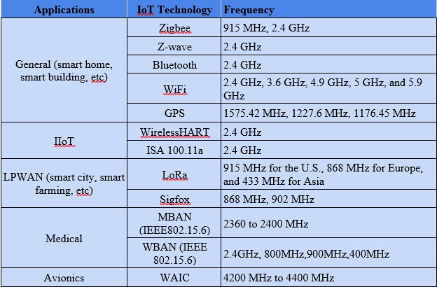
Table 1: Operational frequencies of various IoT technologies
Whip Antennas and Ground Plane Considerations
Besides considering bandwidth, there is a notable space factor. Whip, rubber duck, and paddle antennas have the benefit of modularity, as they are not integrated onto the PCB of the IoT device, and can therefore be more convenient for prototyping. These are the most common type of monopole antennas, specifically, the quarter-wave whip. Most antennas have two halves that meet at a feedpoint; a dipole has two radiating elements that meet at the feedpoint, while a monopole antenna replaces the second one with the ground plane.
Oftentimes, the coxial cable’s shield serves as the ground plane of coax-fed monopoles like whip antennas. Large monopole antenna installations will likely have quarter-wavelength radials, mounted perpendicular to the antenna. An ideal ground plane reflects waves such that the radiation pattern on the back-side of the ground plane appears to have another identical monopole antenna; creating the radiation pattern of a center-fed dipole. Real ground planes, however, do not quite accomplish this “virtual image” antenna, but it is still critical that there be a sufficient conducting ground plane (ƛ/4) relative to the antenna. Anything less can impact the radiation efficiency (proportional to ground plane resistance), impedance, resonant frequency, and ultimately its performance. Compared to the lesser used dipole antenna, the monopole has a lower angle of radiation allowing for a longer propagation range particularly at low UHF frequencies.
Whip antennas can also be designed to be ingress protected (IP) and can also come with IP ratings such as IP67 or IP68. This is particularly important in outdoor or harsh industrial environments where water, dirt, oil, and chemicals can damage any external antennas.
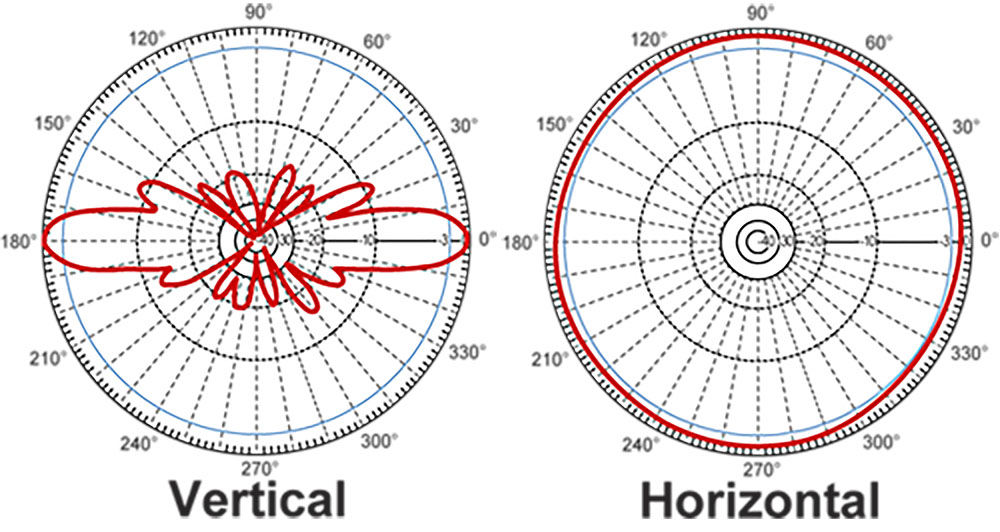
Figure 3: Sample radiation pattern of a whip antenna. These antennas can be encased by durable fiberglass radome for a weatherproof seal.
Patch Antenna Considerations
Patch antennas are often used in IoT devices with GPS capabilities as signals transmitted by satellites are often either right-handed circular polarization (RHCP), or left-handed circular polarization (LHCP), while patch antennas can be designed for dual polarization, which is often reconfigured by switching a perturbation element with PIN diodes or RF MEMS devices. With that being said, there are still many patch antennas that will exhibit only one type of polarization between linear, RHCP, or LHCP so it is critical to choose a polarization matching the transmission.
Chip and PCB Antenna Considerations
IoT devices with embedded antennas like chip and PCB have the benefit of fitting into small spaces, shrinking a sensor node’s dimensions. Composed of conductive traces, PCB antennas often exhibit higher gains than their chip-based counterparts. There are various antenna topologies for PCB antennas including inverted-F, L, and folded monopole. The ground plane is of particular importance in the generation of PCB antennas as a smaller ground plane can constrain design significantly with a much narrower functional bandwidth, lessened antenna radiation efficiency, and modified radiation pattern. As with any antenna, the radiative element’s volume is directly proportional to its gain and (oftentimes), embedded PCB antennas take up lots of space on the board. Nonetheless, sensor nodes implementing a PCB antenna have the characteristic of maintaining a relatively flat shape that could allow for them to be more readily encased and mounted in any environment.

Figure 4: PCB antennas come in a variety of topologies. While this antenna comes with a coax feed with a U.FL connector, many PCB antennas are traces that are directly on the device board with a microstrip transmission line feed.
Omni-directional chip antennas generally have a cardioid-shaped radiation pattern, and—not surprisingly—exhibit some of the lowest gains. When tested in real environments, these antennas can show a higher directionality in a particular direction, and may have a more ideal orientation for generating a link. Wearable IoT applications like WBANs will most likely require the use of chip antennas due to its benefits of size, with the acceptable trade-off of shorter link distances.
Directional Antennas for IoT
Directional antennas like Yagi and sector antennas can either be used to extend a transmission’s range or for IoT base stations. The mechanical shifting of a high-gain directional antenna will likely provide a larger link distance than omni-directional antenna structures. Yagi antennas, for instance, are often used in Supervisory Control and Data Acquisition (SCADA) systems for IIoT, allowing for increased data throughputs and reliability. Panel (sector) antennas typically exhibit a wider beamwidth than Yagi antennas are often used in SigFox, LoRa, and WLAN base stations as multiple structures can be mounted together, providing 360 degrees of coverage.
Other Antenna Considerations: Internal Noise and External Obstacles
Besides considerations specific to the antenna topology, there are more general obstructions that can prevent a signal from transmitting. Certain onboard components can generate spurious signals that can prevent proper signal transmission/reception. This must be adequately analyzed, either through simulation software or test (or both) in order to minimize noise in the RF front end. Moreover, obstacles inhibiting propagation like metal housing, require external antennas for signals to reach a gateway or end-node. Environmental obstacles like buildings and mountains can cause fading and other multipath effects preventing proper uplinks/downlinks. This, however, may only be an issue for systems with a much longer link distance. Ultimately, the only way to ideally design an IoT system is experimentally troubleshoot with component, antenna, and node placement, along with casing materials. Table 2 lists some of the measures that can be taken to improve an IoT device’s range.
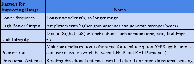
Table 2: Factors for improving range
A Multi-Faceted Problem
Just as there are many IoT standards and protocols out there to fit the various IoT applications, so are there a variety of antennas to help radiate all of these signals. Industrial wireless sensor networks (IWSN) may require sensor nodes (and antennas) that are highly reliable despite harsh environmental factors that can reliably get firmware-over-the-air upgrades in order to maintain proper security measures. Smart farming applications that likely leverage either WLAN or some form of LPWAN (or both) would also require IP rated antennas that are external to the casing. Most MBAN applications would probably require wearable modules with chip antennas that have very strict power specifications and ultimately communicate with a controlling device via a wireless link. Smart home and smart appliances may not be as strict on power, but the antennas would likely need to fit into a case, small or flexible antennas may be used in these applications. Antennas structures can vary significantly to best fit the transmission characteristics of any particular IoT application.

