Cavity-based filter performance is determined entirely by geometry. Even though the devices are tuned, it can be challenging to size all the components such that the tuning elements are effective to meet desired synthesized response. 3D electromagnetic (EM) geometry creation and simulation for cavity-based filters is generally very time intensive. Thus, the designer developed a complete “synthesis to implementation” process for helical, cavity-based bandpass filters, enabling, within one integrated project, the rapid exploration of new designs through changes in a small number of key global parameters. By leveraging reusable, parameterized 3D EM building blocks for cavities and resonators in the filter, the synthesis and design stages are simplified, and the design is then highly re-usable.
RF microwave circuit design software was used to completely capture and automate the entire filter design process. A hierarchical modeling approach was used for the cavities that included optimization of the circuit model in the circuit software and verification using EM simulation. The entire process took only six hours thanks to the single, simple flow from synthesis to design to verification and then to implementation. First pass success was achieved on three filter designs, as well as a 5x reduction in time for 3D EM structure creation of the filter family due to the cascadable building block nature of 3D finite element method (FEM) EM parameterized cells (Pcells).
The Design Flow
Requirements for this bandpass filter design encompassed three bands (215 MHz, 380 MHz, and 540 MHz) with high Q and low loss for a series of five cascaded cavities, each with a tuned, helical coil. Figure 1 shows the constructed geometry in the EM simulator. Ports 1 and 2 are for the coaxial feeds, and Ports 3 through 7 are used to tune the filter.
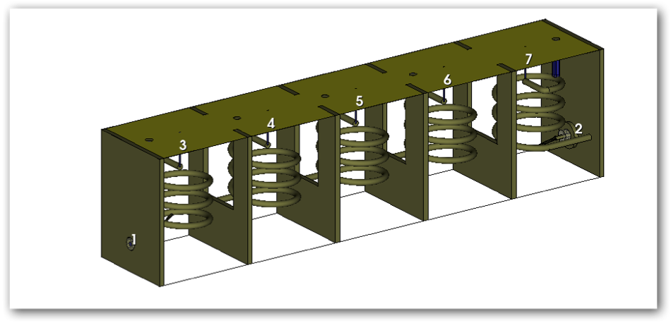
Figure 1: 3D model shown in NI AWR Design Environment™ Analyst™ 3D FEM simulator.
The design and manufacture of this filter presented a number of challenges, as is typical of this type of filter design. First, the filter was designed using ideal elements and traditional filter theory. Optimizations were carried out to get the required response. The first challenge was to get the ideal filter response into an actual, physical, cascaded cavity filter topology. EM simulation was heavily used because the simulator for this application offers the ability to create 3D parts as Pcells that can be repeatedly used in the final layout. This made model creation faster and easier, as the steps from individual cavity design to the final five cascaded sections involved connected similar shapes. The shapes were created using parameters so that the actual geometries could be quickly changed without having to redraw the structures in a 3D layout editor. In fact, the final filter was created by using only three basic 3D components: the cavity with the coil, the end plates with the coaxial feeds, and the interior separation walls with the coupling slots.
The resonators and coupling slots were tuned using tuning screws, in which a post needed to be inserted into the cavity the correct distance to get the right filter performance. The helical resonators and cavity dimensions were initially synthesized using Zverev’s published equations and then optimized using 3D EM simulations with the tuning screws inserted at half and full depth in a single cavity and sweeping the parameterized dimensions of the resonator coil. Similarly, the inter-cavity-tuned coupling ranges were sized using a dual cavity 3D EM model and sweeping the slot dimensions with a tuning screw inserted at half depth.
The full filter 3D EM simulation model was optimized and tuned to the synthesized Chebyshev filter response using the published co-simulation techniques of Dr. Dan Swanson, where ports are added to the resonator elements to allow the tuning screws to be co-simulated in a linear simulation with appropriate equivalent models connected only to the S-parameters of the full 3D EM model. This technique required only a single or very few time-intensive full 3D EM simulations to prove the design instead of a full simulation for every tuning screw depth change.
The filter was constructed for EM simulation by cascading the 3D cells together in a 2D layout. The 3D cell was then drawn using the EM simulator’s 3D editor, and the parameters used in construction were exported into the circuit design environment (Figure 2).
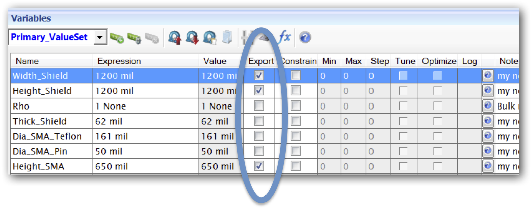
Figure 2: Parameters used in construction of the filter were exported back into the circuit design, 2D environment.
The cavity sections were tuned by placing capacitances across the ports that represent the tuning stubs. A simulation was carried out, correlating the capacitance to the length of the tuning stub for an individual cavity. Optimization was carried out on the capacitors, and the tuning stub lengths were derived.
Fabricating the Filter
The actual fabrication of the filter was carried out quickly and inexpensively by using an LPKF PCB mill to precut the cavity walls, slots, and housing from double-sided, copper-clad FR4, using DXF artwork generated in the circuit project. Figures 3a and 3b show the panel artworks from the circuit software that were used to create the precut pieces with the LPKF machine.
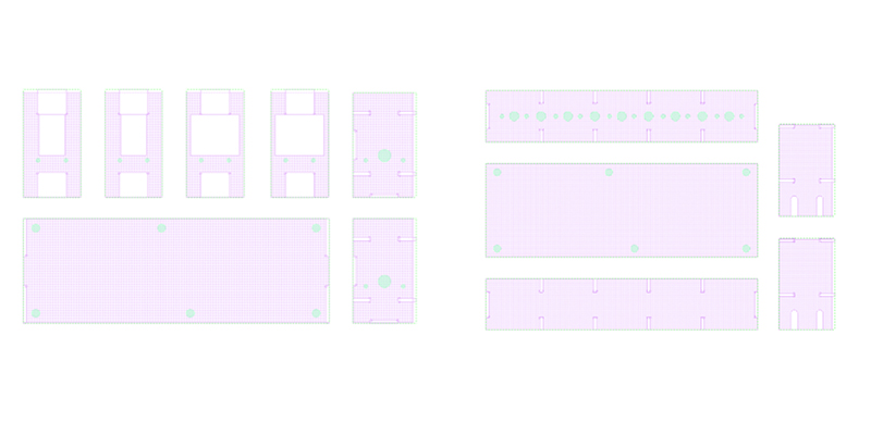
Figure 3a and b: Panel artwork from the circuit software used to create the precut cavity walls, slots, and housing.
The resulting cavity-building blocks were then assembled, similar to assembling a model airplane from thin, flat, die-cut balsa wood pieces. The helical resonator coils were wound on a 3D-printed plastic former from appropriate diameter solid conductor household wire. Final assembly was then carried out by inserting the coils and tuning screws. A wooden dowel was used for mechanically supporting the free end of the coils.
Figure 4 shows the completed 215, 380, and 540 MHz bandpass filters combined into a switched filter bank.
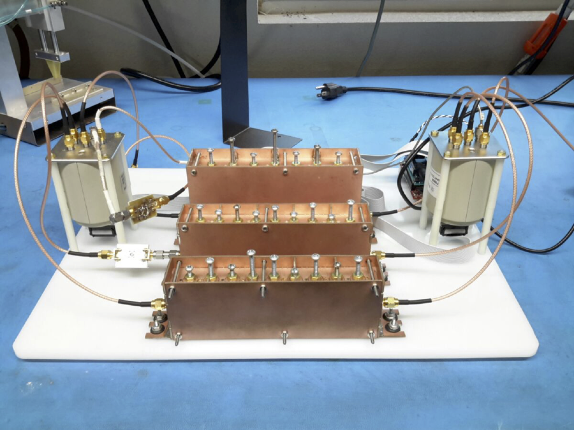
Figure 4: Filters combined into a switched filter bank.
Tuning the Manufactured Filter
The completed filter was then tuned using a technique developed by Ness3. Initially, all the resonators but the first one were shorted out, and the group delay was adjusted to the desired value. Then, each succeeding resonator was tuned using the group delay until the final filter response matched the simulated goal.
Simulated and Measured Results
Typical measured results are shown in Figure 5. Agreement between simulated and measured results was considered excellent. First pass design, construction, and verification of the filters were achieved.
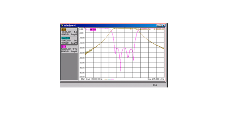
Figure 5: Measured results of 215 MHz filter perfectly overlaid on the simulated data imported into the vector network analyzer (VNA).
Conclusion
This article has described the design and manufacture of a family of high Q cascaded coil-in-cavity filters that were achieved with first pass success. Extensive use was made of 3D EM simulation to design the coils, cavities, and apertures. The integrated platform enabled the designer to work seamlessly between the circuit design software and the 3D EM simulator.

