Dynamic spectrum sharing of 5G and LTE networks addresses the need for spectrum, particularly at mid-band frequencies. Here’s how it works.
Initial 5G network deployments took advantage of underutilized unpaired spectrum that use time-division duplex (TDD) at mid-band frequency ranges such as 3.5 GHz. Unfortunately, most of the spectrum below 6 GHz is paired spectrum using frequency-division duplex (FDD) that network operators use for their 4G LTE-Advanced networks. Because LTE’s FDD-based spectrum assets must remain in place, network operators must choose between acquiring new spectrum or re-farming spectrum already in use. Both options are costly.
The 5G NR standard lets radios adapt to existing LTE deployments and share the spectrum originally dedicated for LTE. The enabling feature, dynamic spectrum sharing (DSS), is part of the overall mechanism that lets 5G NR and LTE coexist while in the same frequency band.
Short-term DSS enables network operators to deploy 5G NR using their lower frequency bands, typically targeting frequencies below 1 GHz. To date, this is still non-standalone (NSA) mode and requires the combination with an LTE anchor, typically mid-band 1 GHz to 3 GHz.
For DSS to work properly, 5G radios must yield a frequency to LTE radios because LTE radios in service today were not designed for sharing. Therefore, it’s up to the smarter 5G radio to get out of the way when LTE radios need the spectrum.
The MBSFN awakening
As in every wireless communication standard, receivers need to synchronize to downlink signals. 5G NR is no different and uses synchronization signal blocks (SSBs) for that purpose. When sharing the spectrum with LTE, the 5G NR needs a “gap” in time to transmit these SSBs. LTE configures Multimedia Broadcast Single Frequency Network (MBSFN) subframes to periodically allow 5G NR’s SSBs.
The network can configure six out of ten subframes forming the LTE radio frame to become MBSFN subframes. Based on the 3GPP standard, this could be subframes #1, #2, #3, #6, #7, and #8 within one radio frame. The LTE network broadcasts the applied configuration with system information in block Type 2 (SIB2). A standard LTE terminal reads in the MBSFN configuration from SIB2 and ignores the subframes configured for broadcast.
Figure 1 shows an example of the MBSFN configuration in a commercially deployed LTE network that uses DSS. The LTE network configures the allocation mode to be four radio frames, which means the given configuration repeats across a total of 40 subframes.
Three of these 40 subframes are MBSFN, which reduce the LTE system capacity by 7.5%; the LTE network can no longer use these subframes for standard data transmissions. These subframes can now be used to carry 5G signals and channels.
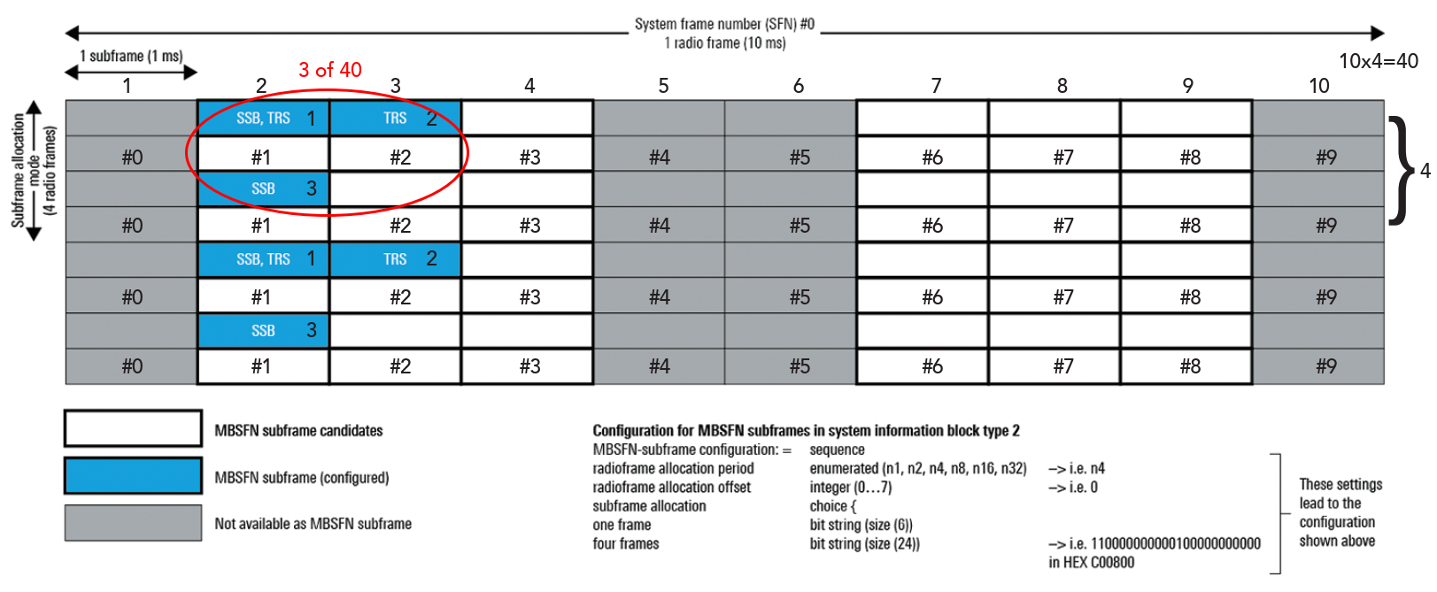
Figure 1. MBSFN subframe configuration in SIB Type 2. The first three subframes of the upper 40 subframes are MBSFN subframes.
DSS initially aims at low-band deployments with carrier frequencies below 3 GHz, which results in a maximum of four SSB indices transmitted. The general guideline conveys the transmission of these four SSBs to the first half-frame (5 msec) of a radio frame. The mapping principle depends on the physical layer numerology.
For initial DSS deployments, 5G NR operates at the same 15 kHz subcarrier spacing as LTE. For a subcarrier spacing of 15 kHz and carrier frequency below 3 GHz, the start symbols for mapping the four possible SSB indices are symbols #2, #8, #16, and #22. The first subframe within an LTE radio frame that is an MBSFN subframe candidate is subframe #1.
Due to the SSB mapping principles for 15 kHz subcarrier spacing, known as Case A, SSB indices #0 and #1 cannot be transmitted, as their mapping occurs in LTE subframe #0. That leaves SSB indices #2 and #3 as their mapping occurs in symbols 16 and 22. The default transmission periodicity for SSBs is 20 msec. Thus, an MBSFN subframe is required every 20 msec, which is fulfilled in Figure 1.
In a real deployment scenario, the network sends only one SSB index. The reason is hardware-related. Leading infrastructure providers claim to enable DSS by a simple software update. The antenna configuration of already deployed hardware does not, however, necessarily support beamforming; it is even more unlikely for equipment that uses low-band spectrum. This means creating several coverage beams, where each beam carries an SSB index directed to a specific area of the serving cell, is not feasible at all.
The need for MBSFN subframes
In Figure 2, the transmitted SSB index is #2 and the diagram further gives a detailed overview of 5G NR signals and channels mapped within an MBSFN subframe.
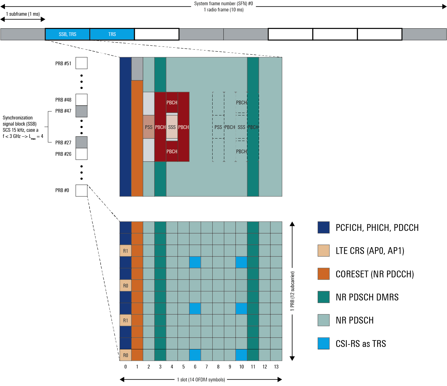
Figure 2. 5G NR transmission in LTE MBSFN subframes includes a non-MBSFN region defined at the beginning of each subframe.
Fig. 2 shows a non-MBSFN region defined at the beginning of each subframe, that can be one or two OFDM symbols long, depending on the overall available signal bandwidth. This region carries the required control channels for LTE, such as physical hybrid ARQ channel (PHICH), physical control format indicator channel (PCFICH), and the physical downlink control channel (PDCCH), including LTE’s cell-specific reference signals (LTE CRS).
Therefore, any 5G NR transmission can only start at OFDM symbols #1 or #2 within an MBSFN subframe. The second OFDM symbol (symbol #1) in the slot carries the Control Resource Set (CORESET), and the initial symbol l0 for the first transmission of the demodulation reference signal for the data channel (PDSCH DMRS) is the fourth symbol (symbol #3). The support of mobility requires the transmission of an additional symbol for the demodulation signal. Based on the definitions in the standard, this is the twelfth symbol (symbol #11).
Fig. 2 also shows the position of SSB index #2 and #3, but again only index #2 is transmitted. That has to do with the second signal component, which requires the availability of MBSFN subframes: tracking reference signals (TRS). Index #3 would collide with the mapping of these 5G signal components. As there are no cell-specific reference signals in 5G as there are in LTE, the device maintains synchronization based on channel state information reference signals (CSI-RS) configured for time-frequency tracking.
Enabling 5G NR in standard LTE subframes
The 5G NR standard requires the transmission of channel state information reference signals (CSI-RS) over two consecutive slots, when configured as tracking reference signals (TRS). This corresponds to two consecutive subframes when the subcarrier spacing is 15 kHz. The second requirement is that two resources (= symbols) within the slot are available to transmit this CSI-RS configuration. These two resources per slot could be symbols {4, 8}, {5, 9} or {6, 10}, where the latter is the mapping that avoids collision with SSB transmission if SSB index #2 is transmitted. The periodicity for TRS as CSI-RS is flexible. However, 40 msec provides adequate accuracy and results in the requirement of having two MBSFN subframes available every 40 msec, which the network enables with the MBSFN configuration shown in Fig. 1.
Rate matching for LTE cell-specific reference signals
Transmitting 5G NR in three out of 40 subframes (see Fig. 1) does not provide any substantial capacity for any 5G NR deployment. To overcome this situation, DSS enables the transmission of 5G NR in standard LTE subframes not configured for MBSFN. In standard LTE subframes, there are still signal components that need to be avoided by any 5G NR transmission, even if the scheduler in the LTE base station does not intend to use this subframe for data transmission.
Besides the control channels at the beginning of every LTE subframe, cell-specific reference signals are always present in each subframe. Their mapping in the time-frequency resource grid depends on the physical cell identity and the MIMO mode (2×2 or 4×4). Figure 3 gives an overview of these signals’ mapping up to four antenna ports.
The 5G NR base station scheduler uses a rate-matching algorithm to puncture these resource elements, thereby avoiding any transmission on the resource elements carrying LTE CRS. The network signals the required information of frequency, bandwidth, and the number of antenna ports to the device.
Besides this necessary information, the system indicates further the MBSFN configuration and a frequency shift parameter vshift. The shifting parameter depends on the physical cell identity and follows a modulo-6 operation. The MBSFN configuration is required, as the scheduler does not need to avoid any LTE CRS in MBSFN subframes, as there aren’t any transmitted. The Abstract Notification Syntax 1 (ASN.1) in Figure 4 gives a summary of the transmitted parameters.
Alternative position of additional PDSCH DMRS signal
The second required feature is the support of an additional position for the mapping of 5G NR’s Physical Downlink Shared Channel (PDSCH) Demodulation Reference Signal (DMRS). Based on a standard LTE subframe, with the LTE control channel and CRS present, assuming the scheduler does not schedule any PDSCH, the remainder of the subframe is available to 5G NR.
Therefore, the CORESET and the 5G NR PDSCH with rate matching active, including its DMRS, are mapped on the LTE subframes’ available resource element. As explained earlier, a second PDSCH DMRS is required to enable mobility. The symbol position depends on the number of available symbols for the 5G NR transmission.
If we assume that the LTE control channels occupy only the first symbol of the slot, then 13 OFDM symbols are left for transmission with symbol #11 carrying the additional PDSCH DMRS. The PDSCH DMRS transmission would, however, collide with LTE CRS already occupying certain resource elements within that OFDM symbol; see Figure 5.
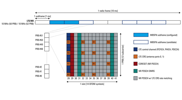
Figure 5. An alternative position for 5G NR’s additional PDSCH DMRS (symbol 12 instead 11) avoids a collision.
In this case, the solution is to move the transmission of the additional DMRS position by one symbol to symbol #12. This change only applies if the 5G terminal has indicated its support of this feature when transmitting its UE capabilities towards the network, and the network configuration itself meets two specific settings:
- The position of the initial PDSCH DMRS transmission is l0 = 3. The devices decode this information from the Master Information Block (MIB) transmitted via the Physical Broadcast Channel (PBCH) as part of the SSB transmission.
- The network has configured the device via dedicated RRC signaling with the LTE-CRS rate matching algorithm that we discussed earlier.
Where is the “dynamic” in DSS?
So far, we have discussed a semi-static configuration of both LTE and 5G NR to enable the use of specific subframes for 5G NR when LTE is not present at all, or mechanisms that allow 5G NR to transmit in LTE subframes that are not used by LTE. The question remains, is there a way for LTE and 5G NR to share a subframe, and for both to transmit control information and data? The answer is yes, of course, but it very much depends on the infrastructure vendor.
To put the dynamic to DSS, the infrastructure vendor typically requires the network operator to co-locate 4G LTE and 5G NR radios and connect them to the baseband processing unit that controls a cell and thus its frequency band. In that case, the scheduler — while monitoring the cell load, type of services requested by the terminals, and ultimately knowing how many LTE and 5G devices connect to this cell can use this information to assign resources towards LTE or 5G dynamically.
According to public announcements of infrastructure vendors, this situation is assessed on a 1 msec basis and can, therefore, change rapidly depending on the load situation in the cell. Nonetheless, the dynamic aspect of spectrum sharing is a proprietary characteristic of the used infrastructure vendor.
 Andreas Roessler is a technology manager for Rohde & Schwarz. He focuses on 3GPP’s 5G New Radio (NR) standard and advancing 6G research topics. His responsibilities include strategic marketing and product portfolio development for Rohde & Schwarz test and measurement division. Andreas has more than 15 years of experience in the mobile industry and wireless technologies. He holds an MSc in electrical engineering with a focus on wireless communication.


Did 3GPP define MBSFN for US market ? ( for N5, N41, N66)
Do you think MBSFN is benefical also for European markets? ( N1,N3 DSS applications)