Metal-insulator-metal and metal-oxide-metal capacitors popular in analog/RF designs because of their desirable characteristics. By extracting parasitics from your models that are important in your design, you’ll get a robust circuit.
Analog and RF IC designs are essential to many of the communications technologies now in use and in development, including 5G cellular technology, mobile applications, and the Internet of Things (IoT), a network of smart devices connected to the internet to share data. End users across different industries and services, from business to education to entertainment to transportation, are looking for improved integration, more efficient power management, and high RF/ extremely high frequency (mmWave) [1] performance.
Process technologies using fin field-effect transistors (FinFETs) and fully-depleted silicon-on-insulator (FDSOI) transistors allow designers to integrate a wide spectrum of high-performing RF and mmWave transistors with logic devices to address a variety of market segments, including mobile, IoT, analog, and RF/mmWave [1,2].
While 5G will deliver unprecedented bandwidth and multi-gigabit data rates, it also faces power management challenges and high-power linearity requirements [3]. Capacitors are an integral part of many analog/RF design applications, with metal-insulator-metal (MIM) and metal-oxide-metal (MOM) capacitors being widely employed. Unfortunately, process variations and in-context issues can affect capacitive accuracy and matching requirements, making accurate extraction and modeling both essential and more complex. In this article, we’ll focus on the design and parasitic extraction (PEX) challenges of MIM/MOM capacitors in RF design applications, and propose best practices to solve those challenges, illustrated by experimental results.
Capacitors
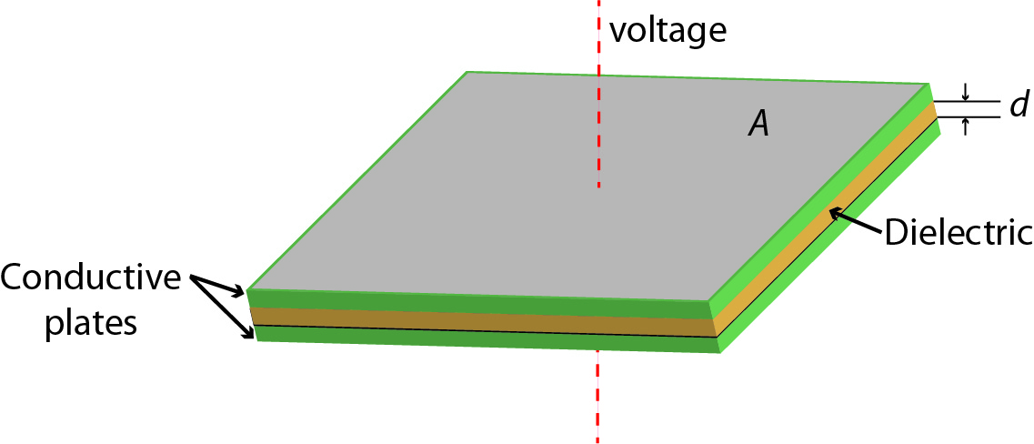
The simplest type of capacitor consists of two overlapping parallel plates separated by a dielectric (Figure 1). The plates act as electrical conductors and the dielectric as an insulator. When a voltage difference is applied across the conductors, an electric field is created across the dielectric, which causes a positive charge to collect on one plate and a negative charge on the other plate. The capacitance (C) between the plates is a function of the area of the overlapping plates (A), the dielectric constant (ε), and the distance (d) between the plates (C=εA/d)it is also the ratio of the electric charge (Q) on each conductor to the voltage difference (V) between them (C=Q/V).
 Capacitors in analog/RF design
Simple plate capacitors require a lot of area, though, and can’t be tuned. In a bandpass filter (also known as LC tuning circuits), charge flows between the capacitor plates and through an inductor connected to the plates to store electrical energy in specific resonant frequency bands. Bandpass filters are key components in oscillator, filter, tuner, and frequency mixer designs [4], and are commonly used in analog/RF designs when a tunable frequency source is needed, such as in signal generators, radio transmitters, and receivers.
Capacitor design requirements for analog/RF circuits include low voltage coefficients, good capacitor matching, precision control of capacitor values, and small parasitic capacitance. In addition, designers strive for high reliability and low defect densities in manufacturing [5]. Because of these requirements, on-chip capacitors in a bank must match very precisely, and deliver capacitance density, voltage linearity, leakage current, and a quality factor (Q-factor) that comply with the design specifications. In the past, designers were forced to compromise between the Q-factor and capacitance density. Advanced process technologies now enable smaller feature sizes and an increased number of metal layers. With these technologies, capacitors can be created using multiple vertical metal layers on existing masks, which maximizes both capacitance density and Q-factor, and provides inherent symmetry [6].
Capacitive charge pumps use capacitors to raise or lower voltage; they’re integral components of an analog to digital converter (ADC). In an ADC charge pump, voltage gain is achieved by sampling an input voltage on multiple capacitors, and subsequently connecting each capacitor in series to yield a total voltage equal to the sum of the individual voltages sampled on each capacitor [7]. Due to this relationship, charge pumps require precise capacitance matching, because even a small error on each capacitance changes the output voltage significantly [8].
MIM/MOM capacitors
Metal-insulator-metal (MIM) and metal-oxide-metal (MOM) capacitors are widely used in analog/RF designs because of their desirable characteristics:
- High-capacity density due to minimum width and spacing of metals
- Good matching characteristics due to lateral coupling
- Symmetric plate design
- Superior frequency characteristics and quality factor
- Low cost, due to no additional mask or process steps [9]
Each type, however, has specific pros and cons, so designers must weigh those factors to decide which device is best suited for a particular application.

Tell Us What You Think!