Simulations and signal measurements can provide the insight you need to create a functional private network for industry and factory use.
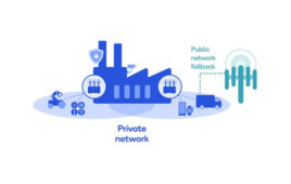
3GPP Release 16 adds support for time-sensitive networking (TSN) integration and other enhancements that support ultra-reliable, low latency communications (URLLC). These enhancements pave the way for 5G private networks that could increase productivity, quality, efficiency, and safety across multiple industries. These 5G private networks – termed “non-public networks” because they operate independently of the available public networks – could bring use cases in energy, supply chain management, retail, healthcare, education, and beyond.
Manufacturing looks to become the most prominent use case for 5G private networks. Private networks serve as the backbone of smart factories, where they connect, monitor, and control the intricate choreography between robotic equipment, monitoring sensors, and production lines. Today, most of these smart factory networks are wired networks that use Ethernet. Replacing these wired networks with wireless 5G private networks will yield obvious advantages, including reducing physical infrastructure and enabling greater mobility.
Smart factories and other advanced manufacturing facilities may benefit from 5G private networks. Unfortunately, these facilities challenge RF signals and the networks that rely on them. Dense metal – including infrastructure and heavy machinery in motion – can create reflect, diffract, and scatter RF signals. 5G private networks operating in manufacturing facilities may also have to contend with interference from other radios such as Wi-Fi and MulteFire. These and other signal impediments can hinder the extreme reliability and latency requirements for TSN and other network technologies that advanced manufacturing facilities require. A small change in network latency can be devastating to manufacturing productivity.
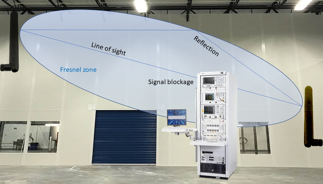
Figure 1. Partially blocking a signal’s Fresnel ellipsoid can interfere with line-of-sight signal paths. (Click image to enlarge.)
How signal blockage affects a 3.5 GHz signal
In the U.S., private networks operate from 3.55 GHz to 3.65 GHz, called mid-band 3.5 GHz. When a 5G signal encounters a metallic object, what happens to the signal depends on the object’s size and shape. If the metallic object is large enough to block the Fresnel ellipsoid of the propagating signal (Figure 1), then it blocks the signal’s direct path; the signal will reflect. The signal may still propagate towards the receiver through reflections or other interactions. Thus, even if the object is large enough to completely obstruct the signal’s Fresnel ellipsoid, that signal may still find its way to the receiver.
If the metallic object is smaller than the propagating signal’s Fresnel ellipsoid, it may not block the signal’s direct path. The wave will continue to propagate toward the receiver, but at a diminished signal power due to partial diffraction and scattering from the metallic object. Such a partially diffracted signal may or may not be able to reach the receiver with sufficient power.
The metallic object’s shape can create a signal blockage that can affect the interaction. If the object is flat, there will be reflection and possibly diffraction from the edges. If the metallic object has curved surfaces, the signal wave will be scattered in multiple directions.

Figure 2. Moving and stationary objects on factory floors can block and reflect RF signals. (Click image to enlarge.)
During the network design and planning stage, engineers can model some effects of signal blockage on a factory floor in a laboratory environment. Because many variables, including the size and shape of the blockage, impact a signal’s strength when it reaches the receiver, you’ll need to perform field testing to determine how a 5G signal interacts with the real-world factory environment. 5G private network running applications that depend on TSN if propagating signals do not reach the devices operating on that network with sufficient power (Figure 2).
Fading considerations in private network design
Before discussing the required measurements, let’s investigate the radio channels. A radio propagation channel is the environment where the radio signal travels from the transmitter to the receiver.
Understanding the signal propagation characteristics in a wireless channel is important for designing any wireless communication system, including private networks. This understanding helps you design the transmission signals and processing algorithms at the receivers. It also helps you to understand the fundamental limits of the radio performance.
Many factors, including the antenna design, thermal noise, and environmental effects (reflections, diffractions, scattering) affect radio signal quality. There are two types of radio fading: large-scale and small-scale. Path loss and shadowing cause large-scale fading while changes in time, frequency, and space domains cause small-scale fading.
The signal strength at the receiver can change because of fading. For example, a radio transmission at 3.5 GHz at 0 dB power has a different data throughput performance than the same transmission at 3.7 GHz in the same environment. Likewise, different distances (space) between the transmitter and receiver will have different performance characteristics.
Industrial environments such as factories have a lot of metal, moving vehicles such as automated guided vehicles (AGVs, autonomous mobile robots (AMRs), and other radio-noise-generating equipment. The fading effects in factories differ from other environments. Hence, private network radio systems designed for outdoor or traditional commercial communications don’t fit well for industry 4.0 environments.
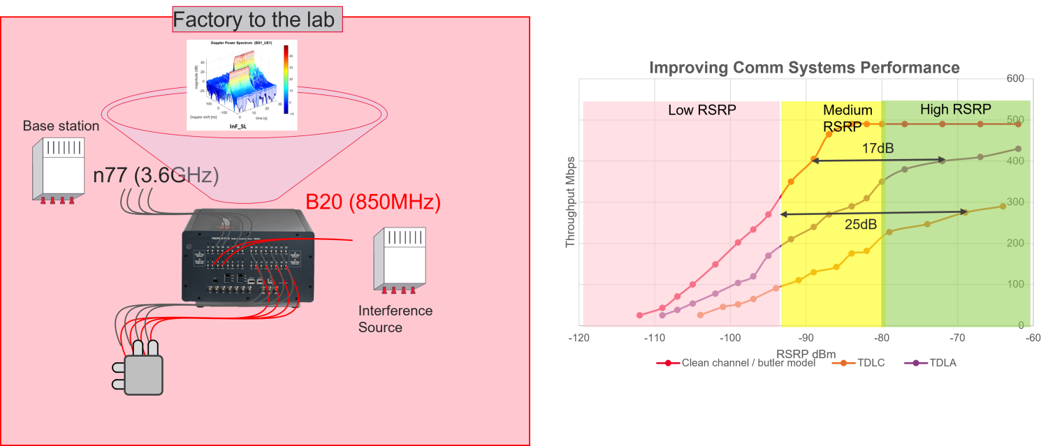
Figure 3. Channel emulation of a factory radio environment provides insight into how actual signals might perform. (Click image to enlarge.)
As a communication system design engineer, you use radio channel models to overcome the challenges outlined above. Modern-day communication systems are complex. Without models, you must design and build the system, go into the field, perform the tests, and, if needed, modify the designs. You’ll need to repeat the steps until the system achieves its desired performance. Radio channel models eliminate this complexity by representing the real-world radio environments in software. You can repeat the tests in your lab until achieving the desired radio performance (Figure 3).
Private Network implementations
Communication RF systems are designed, built, and verified using channel models. Channel modeling precedes the communication systems design. Use
a channel sounder to send a particular training sequence of the radio and measure its performance at various receiving points with specialized radio measurement equipment. This follows the curve fitting and various other methods for generating a channel model for that environment.
Because field environments are unique, there is no guarantee that communications systems can achieve peak performance in all radio conditions. Before installing a private network, you must size and design the networks to meet the installation’s functional and performance needs.
Network planning for an indoor environment involves multiple considerations. The two primary considerations are coverage and capacity. Coverage is provided by the optimal placement, with proper orientation, of radio units throughout the required coverage area. The network needs sufficient signal strength and signal and interference to noise ratio (SINR) at every point in the space. Typical criteria for consideration are 95% reference signal received power (RSRP) or SINR. Lack of adequate coverage and signal strength leads to the following:
- Inability of UEs to find and connect to a network;
- Poor throughput and latency performance;
- Connection drops and increased handovers;
- Increased power consumption by the UEs.
Capacity is provided through the bandwidth of the deployed cells, carrier aggregation, and densification if necessary. Lack of capacity can lead to congestion, low throughput, and high latency for end users.
The initial coverage planning — also referred to as RF planning — involves using modeling software to place hypothetical RF transceivers and measure the signal strengths throughout the building, with appropriate modeling of the propagation environment, including walls, windows, and other barriers. Such propagation modeling provides an estimate, which you must verify using field measurements.
Field RF Measurements
Your field RF assessment objective is to verify that the theoretical designs are as close to the possible real-world performance. Perform the following activities:
- Collect power measurements and 5G metrics at points in space for FR1 and FR2 carriers.
- Compare path loss from the software models to field measurements.
- Estimate 5G coverage and performance based on those measurements.
Engineers typically use a continuous wave (CW) signal source for field measurements. Place a radio unit in the desired location and connect a CW source. Walk through the entire space with a spectrum analyzer to capture CW signal measurements. CW measurements may not, however, accurately indicate the signal strength from a wideband 5G signal. For better results, use a realistic 5G signal for the following reasons.
- The correlation between the actual 5G performance and an RF analysis based only on CW waveform single antenna power measurements will not be great.
- Power measurements alone will show path loss but not the actual channel conditions for multipath and MIMO.
- In all cases, the measurement equipment link budget performance will likely not match the actual 5G deployed equipment link budget performance.
- Having additional 5G measurement metrics will help in optimizing future 5G network deployment and ultimately in optimizing any custom UE and gNB designs.
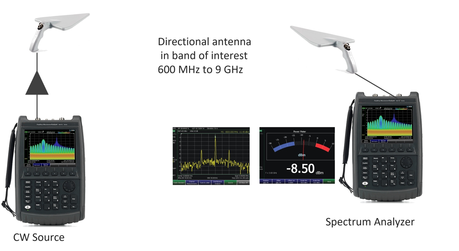
Figure 4. Using CW waveforms can provide some information based on basic path-loss measurements. (Click image to enlarge.)
OTA RF measurements in thefField
Figure 4 shows a typical test setup. A 5G signal generator can generate complex 5G waveforms – downlink, uplink, or both. Depending on the generator, antenna, and analyzer configurations, you can create simple or complex configurations.
The spectrum analyzer/decoder captures the 5G waveform at various physical locations in the field. It then performs the complete 5G frame decoding. The decoded signals are used to compare with the theoretical models. Power measurements alone (Fig. 4) will show path loss but not the actual channel conditions for multipath and MIMO. RF environment analysis using 5G frame waveform decoding (Figure 5) is more accurate than CW or reference signal received power (RSRP) only measurements.
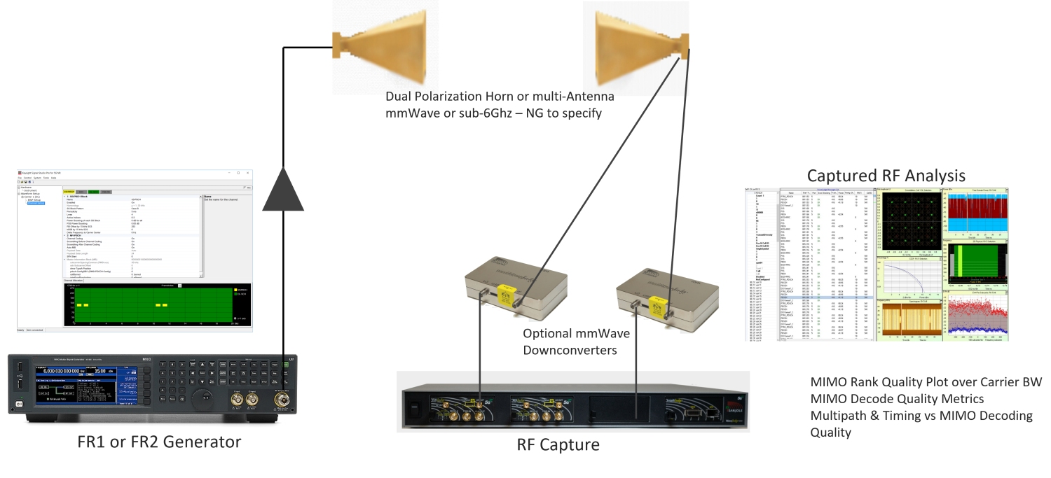
Figure 5. 5G mmWave OTA field analysis can use MIMO with simulated 5G signals.
You can upgrade the setup by using an Open RAN radio unit (O-RU) either as a receiver or as a transmitter and perform a similar analysis. Using this configuration lets you compare the theoretical models with the real-world Open RAN measurements, shown in Figure 6.
Verify RF performance in real-world conditions
Engineers use radio channel models to design, test, and validate complex communication systems. Network engineers plan and design the network using software models in a lab. Industry 4.0 radio environments are, however, complex and unique. Many interference sources can plague an RF network. Fading caused by rich scattering is much more severe. Industry 4.0 applications require private networks with a higher uplink data throughput, high-density connections, ultra-reliable low latencies, and 99.9999% reliability.

Figure 6. Open RAN radio units can function as transmitters or receivers for RF testing in facilities. (Click image to enlarge.)
To meet these performance requirements, you must verify the RF performance in the real-world conditions of their indoor environments and ensure that the RF performance meets their quality requirements.

Tell Us What You Think!