Optical fiber can carry analog RF signals from antenna to receiver with far less loss than coaxial cables.
It’s not unusual in engineering to find solutions to long-standing problems leveraging apparently unrelated technologies. This is the point made repeatedly and effectively by James Burke in his fascinating series Connections, which is still fascinating despite being 40 years old (many segments are available online). It’s not just a matter of linearly building on the work of others but seeing where their progress can be creatively adapted and adopted to a new scenario.
A more-recent example is the use of low-loss optical fiber, originally developed and perfected for conveying digital signals, to replace copper coaxial cables which had limitations due to attenuation, distortion, and bandwidth. Now, these same optical fibers are being used as the conduit for wireless signals normally referred to as “RF” (radio frequency) but in a unique, non-obvious way that seems almost incompatible with the original intent of that optical medium.
This FAQ will explore the use of optical fiber for RF links, in a technique known as RF over fiber or simply RFoF.
Q: What is RFoF?
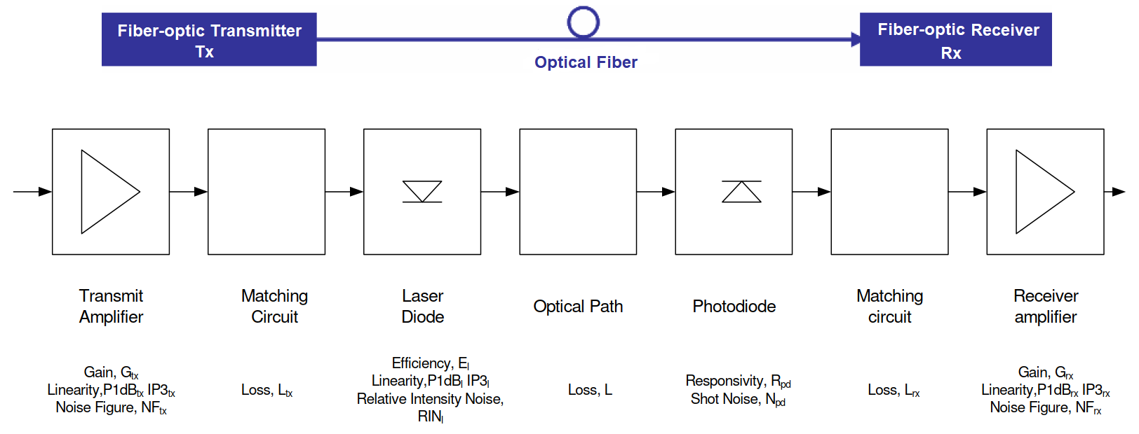
A: In simplest terms, it’s an all-analog way to transfer extremely high-frequency signals (what we conveniently call RF) from point A to a point B many meters away by using optical fiber rather than the more-common coaxial cable called RF over coax/cable, or RFoC, to highlight the contrast), Figure 1.

Figure 1. The RFoF signal path looks like a standard RF system but some RF blocks have been replaced with electro-optical ones and the medium is now an optical fiber. (Image source: Vitalite Communications)
Q: What’s the frequency range for which RFoF is viable?
A: The RF signal of interest can be in the multi-gigahertz range, and the link budget has many of the same parameters as a coaxial-cable link.
Q: Aren’t optical fibers designed and intended for digitized signals?
A: Yes. But although we usually think of an optical fiber link as a medium for digitized signals, it can be used as a linear, analog signal path for analog signals as well.
Q: Wouldn’t it make more sense to just digitize the original RF signal, then use the optical fiber to carry the digitized signals?
A: In many cases, no. in most cases, and especially for the gigahertz RF signals, direct digitization and then on/off modulation of a laser onto fiber is not a viable option due to the bandwidth requirements and the lack of suitable standard A/D converters (cost, power, accuracy).
Q: Which applications are doing this?
A: Applications for RFoF include linking satellite dishes and dish “farms” to control rooms, connecting broadcast booths to communications nodes at major events, conveying GPS and precision timing signals, and providing communications in deep mines or underwater. (Variations in a fiber’s optical properties due to factors such as pressure, bending, or temperature changes enables these fibers to be used as specialty sensors, but that’s another story.)
Q: Why switch from well-known coaxial cable to optical fiber?
A: The reason is that nearly all RF links — and especially the one from antenna to receiver — face the same problem: low received signal power and in the face of noise. Depending on the nature of the link, frequency, distance, and antennas in use, the received signal strength will be nanowatts, microwatts, or milliwatts (with comparable voltage levels). There will also be unavoidable noise on the signal, so the received signal-to-noise ratio (SNR can be as poor a 0 dB (or lower, for deep-space systems) or just several tens of dB.
Q: So what’s the problem? Just boost/amplify the signal with a preamplifier and problem is solved, right?
A: If only it were that simple. The reality is that any amplifier adds noise, so the process of amplifying the signal also degrades the SNR. A specialized, very low-noise amplifier (LNA) may add only around 1 dB, while a typical LNA adds 3 to 5 dB. The problems of minimizing noise due to the LNA are more challenging as the received signal strength is lower or the amplifier subsystem must handle wider bandwidths.
Q: But once you’ve boosted the signal with a suitable LNA, these problems should be over, right?
A: Again, if only it were that simple. The coaxial transmission line from the LNA, which is located right at the antenna, to the receiver front end that may be adjacent or many meters away, adds its own noise mostly due to thermal action. There is also some additional signal distortion.

Figure 2. The difference in attenuation for coaxial cable versus optical fiber is especially apparent as the distance and frequency increase. (Image source: Vitalite Communications)
In addition, the coaxial cable has losses (attenuation), so some of the LNA gain is negated yet you still have the added noise and thus overall degradation of SNR. Very roughly, losses for high-quality coaxial cable are on the order of 3 dB to 5 dB per 100 m over the 10 MHz to 100 MHz band, and 10 dB to 25 dB per 100 m from 100 MHz to 1 GHz, Figure 2. (note: the actual numbers are a function of the particular coaxial cable selected, and there are many loss/performance-related tradeoffs in making that decision.)
Q: So, can’t you just re-amplify the signal at the receiving end if the loss and attenuation is more than acceptable?
A: Sure, but that again adds noise and diminishes the critical SNR parameter. In the end, it’s largely SNR (along with signal strength) which determines the success of recovering a signal and extracting the digital data with low bit error rate (BER) or demodulating the analog modulation with low distortion and high fidelity.
Part 2 (available September 26) explores the RFoF design in more detail.
References
- James Burke, “Connections”
- Vitalite Communications, “What is RF over fiber technology and what are the benefits?”
- Vitalite Communications, “Application Note 037 – Fibre Optic Link Budget”
- Huber+Suhner, “RF-over-Fiber series”
- Everything RF, “What is RF Over Fiber?”
- RFOptic, “RF over Fiber Converters and Bands”
- Wikipedia, “Radio over Fiber”
- Amtele Communication AB, “RF over Fiber”
- Optical Zonu Corp., “RF over Fiber”
- DEV Systemtechnik GmbH, “Wideband RF Over Fiber Systems by DEV”
Related content
- Free-space optical links, Part 1: Principles
- Free-space optical links, Part 2: Technical issues
- Free-space optical links, Part 3: Standard units
- What are RF waveguides? Part 1: context and principles
- What are RF waveguides? Part 2: implementation and components
- Undersea optical-fiber cables do double-duty as seismic sensors, Part 2: Application
- Undersea optical-fiber cables do double-duty as seismic sensors, Part 1: Context
- Directly Modulated Laser Diodes For 4.9G And 5G LTE Base Stations
- Difference between a waveguide and transmission line


This article has sparked my interest. I work in fiber distribution of video data. I often have to investigate RF errors seen at the far-end of the fiber. This is often frustrating when no obvious fiber problems exist; e.g, bad splices, fiber cracks, excessive back-reflection levels, short radius bends, etc.
@Stan,
Come back May 9, 2023 for “Identify, troubleshoot, and resolve PIM issues in wireless networks.”