Performing these three steps can improve mmWave and beamforming performance.
The year 2020 saw the first deployed 5G networks that use millimeter-wave (mmWave) technology. Tests have found that mmWave achieved greater than 1 Gbps downlink speed and up to 3 Gbps peak speed [Ref. 1]. The good news: download speed on a 5G mmWave network is 20 times faster than on a 4G LTE network. Tests have also found that 5G mmWave can cover an entire football stadium — including the parking lot — with only one frequency band to deliver ten times throughput capacity than LTE networks.
The downside: mmWave signals have a shorter range and don’t penetrate obstacles compared to LTE and 5G low-band and mid-band frequencies. The benefits of mmWave, however, far outweigh these drawbacks. Massive worldwide deployment of mmWave is happening. The real question is how do we minimize these impediments of mmWave when it comes to 5G device designs?
Spurious harmonics and intermodulation interference
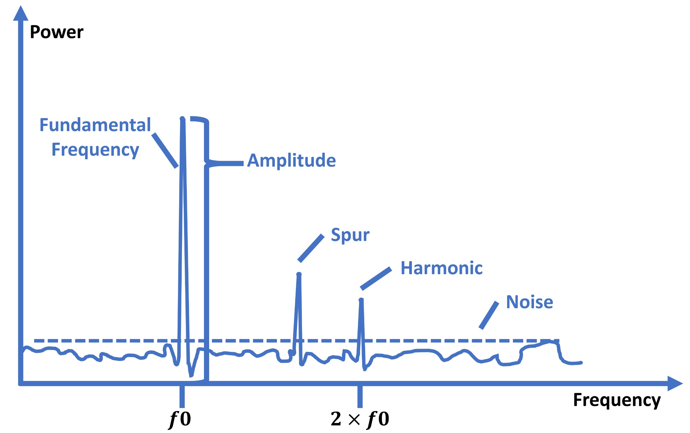
Nonlinearities in power amplifiers and mixers create unwanted signals that appear outside the assigned channel that interfere with other channels. We refer to these intermodulation interference as spurious harmonics. In Figure 1, all frequencies outside of the frequency band of interest (the fundamental frequency) become unwanted spurious harmonics.
Removing spurious harmonics from mmWave signals is difficult because of the short wavelength. Ignoring this issue in device design could violate FCC emission rules on allowable effective isotropic radiated power (EIRP) [Ref. 2]. From an operational point of view, interfering with nearby antenna signal beams could cause other wireless communication devices to malfunction.
Just as with other noise signals in wireless communication, you can’t eliminate spurious harmonics. Identifying the source of harmonics and the interference they cause is difficult. Even once you identify the source, you may have a difficult time reducing its impact.
Performance verification with beamforming
The advantages of mmWave come not only from wider spectrum availability, but from more intelligent radio resource management methods such as beamforming. The complexity of the phased-array antenna system that supports multiple connections simultaneously requires a reliable performance verification process. Engineers need to consider all real-world scenarios and verify that a design works properly before deployment.
One specific example involves accurately verifying the performance of the beamforming signal and antenna in the presence of proper channel models. Because base stations may use a complicated phased-array digital, analog, or hybrid beamforming technology, the connecting 5G devices may use different types of antennas depending on the applications. Therefore, verifying the connection process to find the optimal transmission channel between a base station and a 5G device is crucial, although difficult. With the ultra-short wavelength of mmWave, base stations must perform a computationally intensive process of baseband precoding to select the optimal precoding modulation to apply to the signal streams for each user.
To achieve the best performance, engineers also need to verify 4G and 5G compatibility. Both the 5G infrastructure and devices must support dual-mode 4G and 5G operation to provide a quality user experience in mixed-deployment networks.
Furthermore, we still have pre-coding algorithms, RF phased-array multiple-input and multiple-output (MIMO) system architecture at the base station, and multiple handset antenna placement and radiation patterns to verify. If any of these aspects of 5G mmWave were measured incorrectly, the whole design will fail. Once again, due to the short wavelength of mmWave, setting up the verification can be very challenging as well. A slight misalignment of the equipment can make a significant difference in the results.
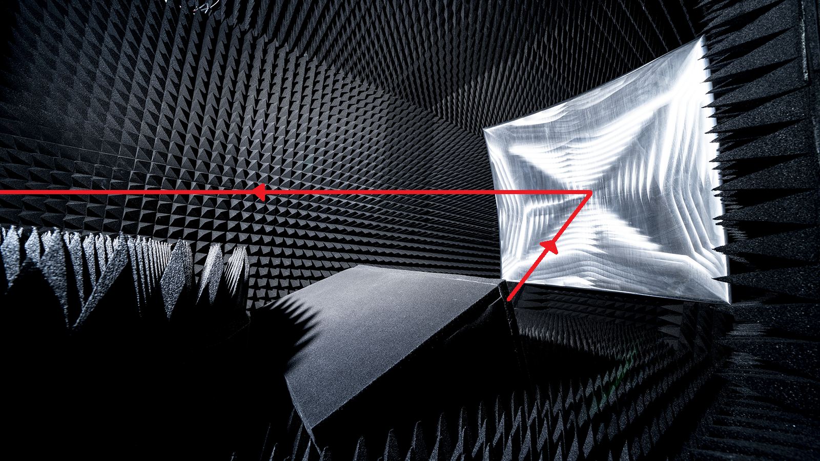
Figure 2 shows a common mmWave device laboratory testing environment. The device under test is in the middle box, which will radiate a signal to the reflector (curved object on the right), then arrive at the receiving antenna, not shown in this photo. The red line represents the signal path. Assume the test is under 100 GHz. That means the wavelength of the signal is around 3 mm, and any misalignment around 3 mm will have a big impact on the test result’s accuracy. In practice, one unnoticeable dent on the reflector, or if the curvature of the reflector is off by a small fraction can lead to a false measurement.
Thus, it usually takes a long time to setup mmWave verification testing and calibrate all the testing equipment. A real-world phase-locked loop measurement can take six hours to set up and calibrate the hardware. Completion of all verification tests can take considerably longer.
Compact package issues
Recall that mmWave signals have a very high path loss, meaning that they cannot travel far, nor can it penetrate obstacles such as walls or trees very well. To provide high data rates and support more traffic, 5G base stations use large amounts of energy. More cost and energy-efficient 5G base stations ease the burden.
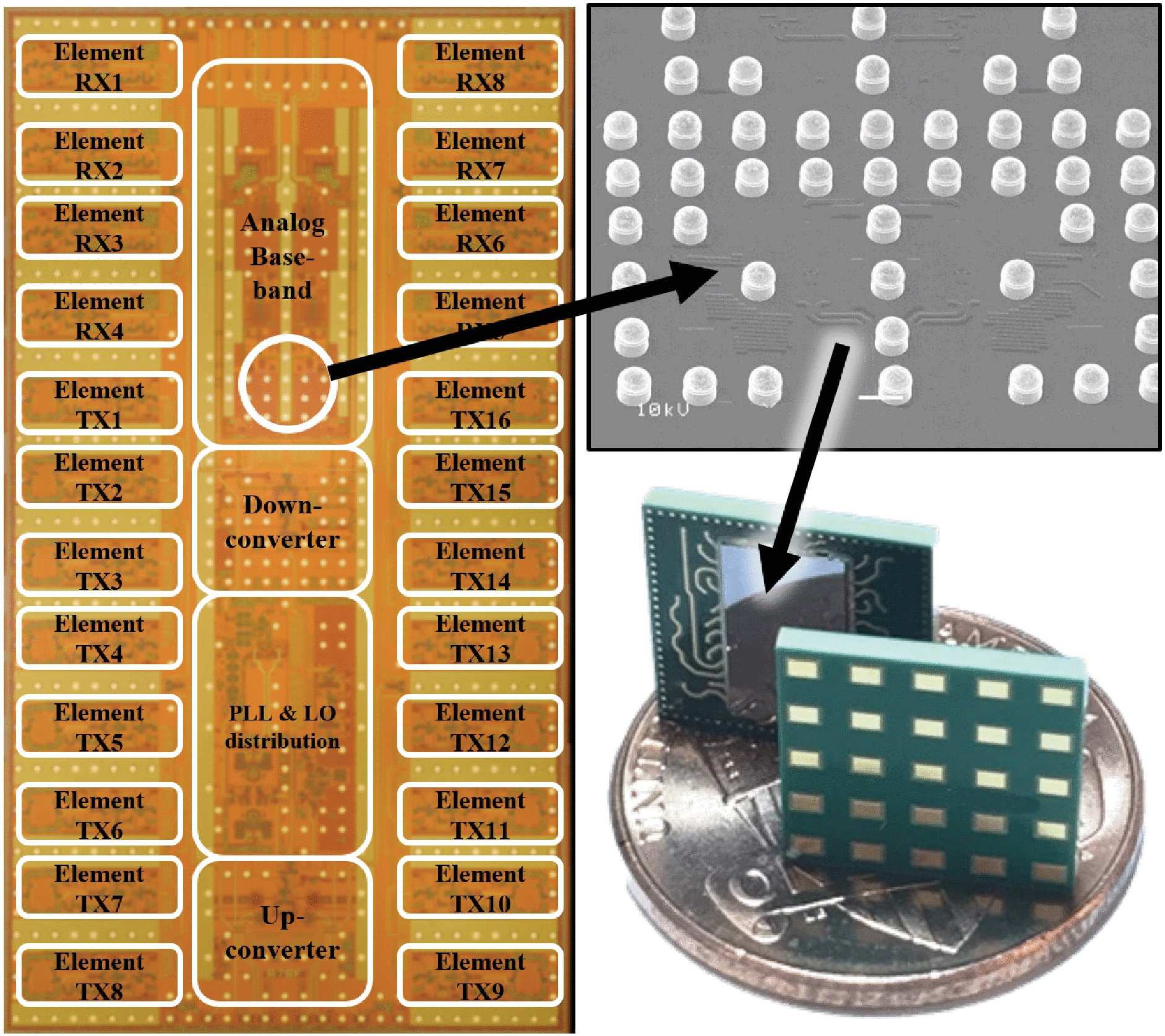
Producing more cost-efficient and energy-efficient base stations sounds relatively easy. Not so. 5G mmWave base stations support much wider spectrum than 4G base stations. Plus, 5G mmWave base stations must support many more features than 4G base stations. Our goal as engineers is to make 5G mmWave base stations as compact and as cost effective as possible, without sacrificing any performance. To provide a better sense of the dimensions involved, Figure 3 is a size comparison between a phased-array chipset and a coin.
The parts in Figure 3 represent only a small part of a 5G picocell. Ultimately, a fully functional 5G mmWave picocell should achieve over-the-air rates of 100 Gb/s with kilometer coverage. In terms of reducing deployment cost, designers should leverage low-cost and traditional manufacturing techniques without using exotic packaging processes and materials.
Prototype troubleshooting complexity
This challenge may not sound as technical as any of the previous challenges, but in practice it is just as prevalent, and the impact could be worse than any of the technical challenges.
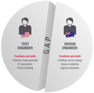
Figure 4. Gaps in mmWave development workflow can hinder communication between test engineer and design engineers.
As mentioned earlier, mmWave device design requires engineers to measure and verify as many RF device characteristics as possible, and there are already many technical design challenges you need to consider before a prototype device goes to the verification phase. Furthermore, as the complexity of wireless technology and application grows, it requires different skillsets to do device design and device verification. Many companies these days often have designated — but separate — departments to work on design and testing. In some cases, design teams and testing teams are even located in different countries as Figure 4 shows. Therefore, exchanging ideas, data, and knowledge between design and test teams might not be very straightforward. Additional time maybe required due to knowledge, functional, and even geographical gaps.
For instance, test engineers can perform antenna measurements, RF parametric, and function/protocol testing. Performance issues not caused by the testing setup can prove difficult to troubleshoot. Design engineers and test engineers to must collaborate to resolve any design issue.
Simulation can help
Simulation lets engineers tackle the challenges posed by mmWave. Our dependence on simulation will grow as mmWave devices become more popular. Simulation may not solve all the challenges outlined above, but it can certainly simplify the design process.
Beginning with spurious harmonics and intermodulation interference, designers can use simulation tools to predict the frequency and direction. Simulation can also help to identify the root cause of spatially radiated spurious harmonics, including the components that generate them and the signal paths used in the RF chain. Designers can also simulate characterization of the spurious harmonics to assess their impact.
Regarding performance verification with beamforming, simulation tools can greatly reduce development time by addressing the signal visualization and verification of many different aspects of 5G end-to-end systems. For example, a simulation tool can simulate 5G link-level validation with a proper phased array antenna to verify the performance of the beamforming design. 5G simulation tools can be used to optimize time, frequency, and spatial resources.
For base station cost efficiency and footprint, designers can use simulation tools to simulate major component blocks of their design, then do a proper linearity and noise figure and gain simulation for the entire system. System-level modeling and simulation lets designers test their designs against multiple variables, without physically setting up testing equipment.
Simulation can also help with prototyping complexity. Design engineers can simulate their design under over-the-air conditions to find discrepancies and predict results. If the simulation and the testing environments are built on a common platform, it is much easier for test engineers to tell if the simulation agrees with the tested results. This makes it much easier to troubleshoot remotely if the design engineers and test engineers are not in the same physical location.
Conclusion
Higher frequency mmWave spectrum can deliver much faster data rates with low latency, while offering greater traffic capacity. These advantages of mmWave unleash the true potential of 5G. In the 5G era, mmWave will play a very important role. It will be heavily used in urban cities, indoor office spaces, transportation hubs, and the industrial Internet of Things.
While mmWave brings significant design challenges to the table, its widespread deployment is inevitable. Device makers and network equipment manufacturers can accelerate their mmWave design cycles by adopting more simulation solutions in their design workflows. At the same time, they also need to improve simulation accuracy, and connect design simulation and prototype test workflows. Simulation provides the shortest path to mmWave market-ready products without extensive investment or sacrificing performance.
References
1. Deploying mmWave to unleash 5G’s full potential, Qualcomm, Nov. 10, 2020. https://www.qualcomm.com/news/onq/2020/11/10/deploying-mmwave-unleash-5gs-full-potential
2. Guidelines for Determining the Effective Radiated Power (ERP) and Equivalent Isotropically Radiated Power (EIRP) of a RF Transmitting System, Federal Communications Commission Publication 412172, https://apps.fcc.gov/eas/comments/GetPublishedDocument.html?id=204&tn=255011
 Xiang Li, Industry Solution Marketing Engineer, Keysight Technologies. Xiang is an experienced wireless network engineer with bachelor’s and master’s degrees in electrical engineering from the University of Manitoba.


Tell Us What You Think!