Power over Ethernet (PoE), a networking feature defined by the IEEE 802.3af and 802.3at standards, enables Ethernet cables to supply power and data simultaneously to network devices over an existing data connection. Approved on September 27, 2018 by the IEEE-SA Standards Board, the IEEE 802.3bt standard lets significantly more power to be passed over the Ethernet link. Here, we discuss why this is significant and how engineers can take advantage of the potential this presents.
Why are we still using wired connections when wireless network architectures are readily available? While wireless connectivity is convenient, there are millions of miles of existing wired CAT5e cable in buildings and homes, so wired connections are still in good use. Plus, wired is more difficult to hack or intercept than wireless (Enterprise networks such as universities are mostly wired) and long wired cables are pretty low cost. If you have a building made of brick, stone, and metal, you may have trouble getting a good wireless signal in many cases (5G is coming with better indoor coverage, but not fully deployable for a while). If you need access to an Ethernet cable signal, you have to cut into the cable – good luck. Furthermore, wireless can be more easily corrupted by other signals and radio waves, while wired cable is often shielded and offers a ‘plug and play’ experience and better Quality of Service (QoS).
802.3bt system architecture
The system architecture uses Power Sourcing Equipment (PSE) that supplies power over the Ethernet cable to the Powered Device (PD). The IEEE 802.3bt standard states, “A PD is the portion of a device that is either drawing power or requesting power by participating in the PD detection algorithm. A device that is capable of becoming a PD may have the ability to draw power from an alternate power source. A PD requiring power from the Power Interface (PI) may simultaneously draw power from an alternate power source” (Ref. 1). A typical PD is a device such as an IP phone, wireless access point, security camera, etc., which receives power from an Ethernet cable. The Power Interface (PI) is the mechanical and electrical interface between the PSE or PD and the transmission medium. This is defined in the IEEE802.3bt standard under ‘PD PI Current Definitions’ section 1.4.324
Previous PoE standards used only four of the Ethernet cable’s eight conductors to carry DC current. The IEEE task force chose to use all eight conductors for 802.3bt. The IEEE Std 802.3bt-2018 Amendment 2 states that “This amendment adds power delivery using all four pairs in the structured wiring plant, resulting in greater power being available to end devices. This amendment also allows for lower standby power consumption in end devices and adds a mechanism to better manage the available power budget.”
The IEEE standards committee had a goal to increase the amount of power delivered from the Power Sourcing Equipment (PSE) to the Powered Device (PD). These nominal power levels are up to 71.3 W delivered to the PD (90 W is sourced from the PSE) while significantly reducing the standby power required for PDs when asleep.
The Autoclass feature
The IEEE 802.3bt standard, section 145.8.8.2, has an optional extension of the Physical Layer classification called Autoclass. With this feature enabled, the PSE determines the actual maximum power drawn by connected PD devices. Autoclass is only defined for single signature PDs (see next section for single-signature definition).
When the PSE implements Autoclass, it will measure PAutoclass when it achieves POWER_ON while pd_autoclass is TRUE. See the section in this article entitled, “An 802.2bt Worst Case example,” which shows a case that does not reach the desired full power sent to the PD. Autoclass will rectify this situation if it is enabled. For more details, see Ref. 2.
Single-signature/Dual-signature
The IEEE 802.3bt brings two new PD topologies called single-signature and dual-signature. The single-signature PD has the same classification, Maintain Power Signature (MPS), and detection signature between both pairs. The dual-signature PD has independently different signatures between both pairs. The 802.3bt standard enables differentiation capability to recognize the difference between a single or dual signature PD connection via the new addition of a Connection Check.
The dual-signature PD will require two parallel PD interfaces because there are two distinct pair sets needed in this topology. The power from each of the PSEs is added together after each PD interface. This is a more costly option; designers may choose a single-signature option at half the cost. Think of a surveillance camera with dual-signature where one pair is connected to the camera and the other pair to a heater or pan/zoom motor.
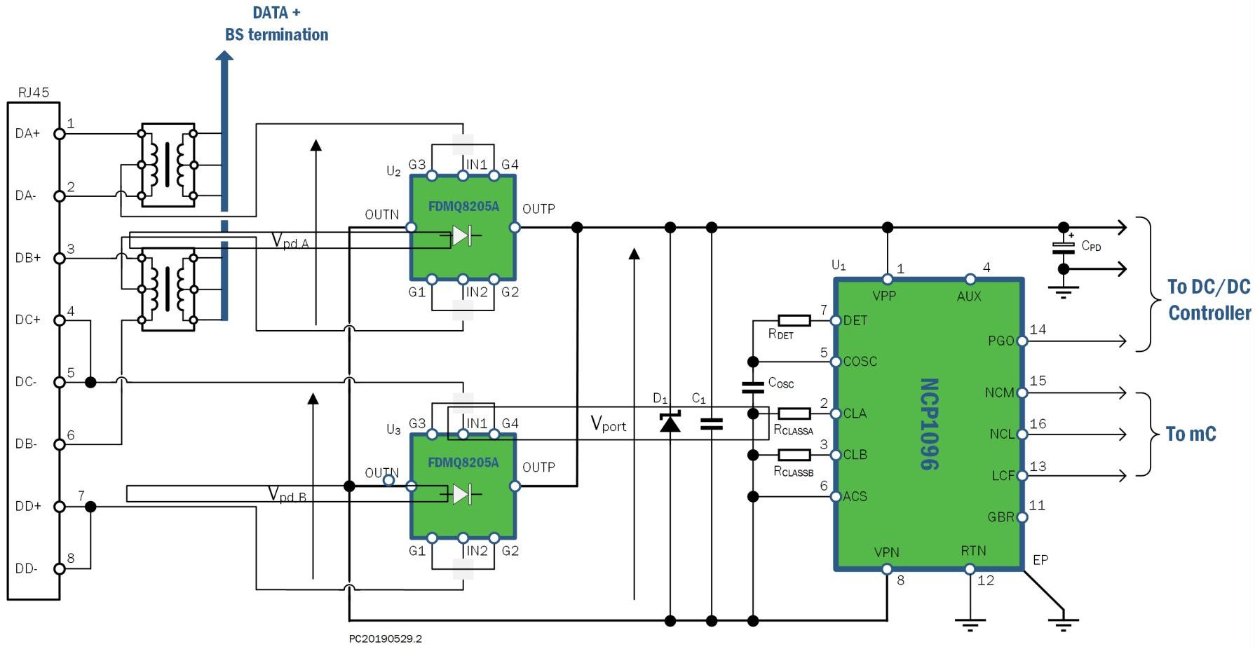
The PD side will also typically need a transformer for each data pair coming from the PSE (for gigabit Ethernet, see Figure 1 where Vpd,B could be for 10/100Base-T), an active bridge rectifier, an 802.3bt PD interface controller and a DC/DC converter. Schottky diodes and resistors and capacitors are also understood as possible parts of the PD additional components.

Figure 1 This application of 802.3bt PD uses two bridge rectifiers and a PoE-PD Interface Controller to deliver power to the load.

Figure 2 A Worst-case channel of 6.25 Ω with a load having constant power of 71.3 W (Class 8). 1.73 A or 0.433 A per conductor, is the highest nominal current that can flow in a compliant system (Image courtesy of Ref. 3)
Figure 2 shows that Type 4, Class 8 PDs may take a maximum of 71.3 W. With the lowest allowed PSE voltage of 52 V, and the worst supported channel resistance of 6.25 Ω, a current of 1.73 A will flow through the cable.
PD side potential issues and possible designer solutions/mitigation
The IEEE 802.3bt standard states that “A PD is specified at the point of the physical connection to the cabling. Characteristics such as the losses due to voltage correction circuits, power supply inefficiencies, separation of internal circuits from external ground or other characteristics induced by circuits after the PI connector are not specified. Limits defined for the PD are specified at the PI, not at any point internal to the PD, unless specifically stated.”
The following points cover areas that you should consider for a truly robust design architecture:
- Be aware of current unbalance due to the other devices in the channel (diodes, transformers, etc.) between PSE and PD. As long as you’re aware of this imbalance, you can employ creative options to mitigate it. This will depend upon the design architecture. Some solid rules are to use a good ground plane as well as wide ground returns that carry large currents.
- Pair-to-pair current unbalance in Ethernet cabling: The problem here is that cable suppliers rarely test or give designers pair-to-pair unbalance specifications; they usually only specify unbalance within a pair.
- Beware of cable heating. There is usually plenty of cable heating data available. As a designer, you need to control the keep the temperature rise. The IEEE task force determined that the limit should be less than a 10°C temperature rise. They used a 300 mA flow in all cable conductors, which is like 51 W power being delivered to the end of every 100 m length of cable with no unbalance. You can try some solutions such as using lower resistance cable to lessen the I2R loss, use fewer cables in each bundle or only partial powering within a cable bundle.
The correct way to determine power dissipation (heating) for any given cable is to use a constant-power sink as the load and a voltage source as the input supply (Ref. 3).
Some cable heating studies will test cable bundles at 2.0 A. So, if a 24 AWG cable is used (Figure 3), that will lead to a power density in the cable of 164 mW/m. The Power Density is power dissipated in the cable per unit length so:
 Rch is based on the resistivity of 24 AWG solid copper at 20oC.

Figure 3 In a 24 AWG UTP channel, and the load is a constant 2.0 A. That makes the channel resistance (Rch) 4.09 Ω.
- There is a nonlinear relationship between the power being delivered to the PD (PDs are a constant power load) and the PSE power output. All PDs vary in their power needs. More current demand by the PD means higher voltage drop in the cable with IR losses. The PD gets a lower voltage than it needs so it calls for more current. As it turns out, using a higher PD voltage at a lower current stabilizes this effect. To be safe, limit the PSE voltage to less than its 57 V maximum.
Testing PDs
If a manufacturer has a demo board or a reference design, always use it for your application. These boards are carefully created with proper routing and grounding techniques to give the best performance of the architecture. Gerber files for the artwork are usually readily available from the manufacturer. Use those in your design. These methods will limit the need for extensive testing of the final design.
For production testing of the design as well as testing in an actual system, there are some good solutions such as Reach Technology’s PoE5 100 W PoE tester or Reach Technology’s RT-PoE5 IEEE 802.3bt Power- over-Ethernet PSE Production Tester. The University of New Hampshire InterOperability Laboratory is the exclusive third-party testing facility for testing PoE certification. Sifos Technologies has a new compact PowerSync Analyzer for IEEE 802.3bt PoE that will help with four-pair testing. The above solutions will help to ensure a robust system.
References
- IEEE Standard for Ethernet Amendment 2: Physical Layer and Management Parameters for Power over Ethernet over 4 pairs, IEEE Standards Association, IEEE Computer Society, IEEE Std 802.3bt-2018 (Amendment to IEEE Std 802.3-2018 as amended by IEEE Std 802.3cb-2018)
- Optimizing PoE Output Power Through Autoclass, Riley Beck, Embedded computing Design, January 2019.
- Practical PoE Tutorial, Chris DiMinico, MC Communications/Panduit; Chad Jones, Cisco Systems; Ron Nordin, Panduit; Lennart Yseboodt, Philips Lighting, IEEE802.org, Berlin, Germany 2017
 Riley Beck is a member of the Industrial and Offline Products division of ON Semiconductor, based in Lindon, Utah, USA, where he manages a worldwide marketing team for the Energy Management Business unit. This business unit primarily focuses on circuit breakers, wired connectivity transceivers and Power over Ethernet devices. He joined ON Semiconductor through the AMI Semiconductor acquisition and started his career as a mixed signal ASIC designer. His background also includes applications engineering for circuit breaker applications focusing on AFCI and GFCI technologies. Riley received his BSEE (2001) and MSEE (2004) in Electrical Engineering from Brigham Young University. In 2014 he completed the MBA Essentials program at the University of Utah David Eccles School of Business.
Related articles


Tell Us What You Think!