Mobile devices have evolved from basic analog phones to digitally enabled smartphones that fit in the palm of your hand. Voice communications are still part of the mix, but voice calls are handled by converting the voice signal from analog to digital and transmitting it digitally. This means that mobile wireless systems are focused on efficient transmission of digital data, usually with an emphasis on high throughput.
To get digital information onto a radio frequency (RF) carrier, we can modify the amplitude, phase or frequency of the signal. We can describe the signal mathematically as:
![]() Where a(t) is the amplitude of the carrier,
Where a(t) is the amplitude of the carrier,
fc is the carrier frequency,
θ(t) is the phase of the carrier
Figure 1 shows the different ways a signal modulates a carrier. Digital data is represented as a binary 0 or 1, which translates into a low or high voltage in an amplitude-modulated waveform. When modulated using frequency shift keying (FSK), the carrier frequency instantaneously changes frequency depending on whether the modulation is high or low. Similarly, amplitude shift keying (ASK) causes a change in the amplitude of the carrier. In Figure 1, the amplitude shift is shown using two non-zero amplitudes, but the modulation technique could also be a simple on/off keying of the carrier. Phase shift keying (PSK) can also be used, causing an instantaneous change in phase according to the digital modulation. Finally, simultaneous phase and amplitude shift can be used together.
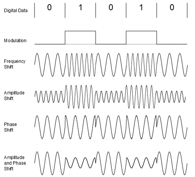
Figure 1. The basic types of digital modulation. All figures are taken from Ref 1.
Quadrature Modulation
As digital modulation techniques have advanced, it has become useful to treat the modulated carrier in quadrature form. That is, the RF carrier equation (Eq. 1) can be refactored to have an inphase term, i(t) and a quadrature term, q(t).
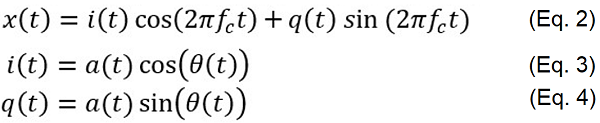 The inphase term controls the amplitude of an inphase carrier, which uses the cosine function. The quadrature term controls the amplitude of the quadrature carrier, using the sine function, which is inherently 90 degrees out of phase from the cosine carrier. Note that i(t), a(t) and θ(t) are all shown as being a function of time because these variables may change according to the applied modulation.
The amplitude and phase of the modulated signal is related to the i and q components by these equations:
 Vector Representation
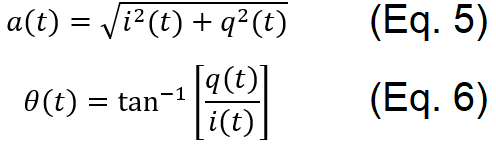
This quadrature representation of the modulated signal enables a vector representation of the signal, as shown in Figure 2. The amplitude of the vector is the length a and the phase is θ. Changing the amplitudes of q and i will result in different values for a and θ.
Figure 2. The vector representation of a modulated signal, with inphase (i) and quadrature (q) components.
These quadrature equations may seem to be just a math exercise, but the quadrature approach maps nicely into a practical implementation. Figure 3 shows the basic block diagram of a quadrature modulator. The modulation inputs, i(t) and q(t), are multiplied by the carrier frequency, with the q(t) carrier shifted by 90 degrees.
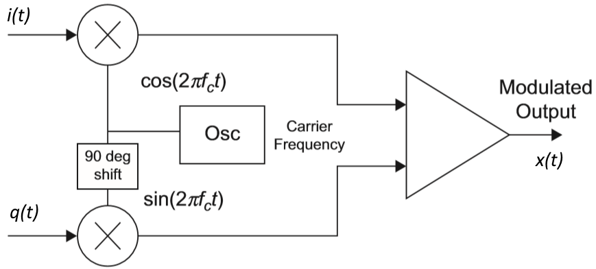
Figure 3. A quadrature modulator combines two signal, 90 degrees apart, into a single modulated output.
We can think of i(t) as controlling the inphase (cosine) portion and q(t) controlling the quadrature (sine) portion. Summing these together creates the desired output signal. This block diagram can be implemented using either analog or digital techniques (or a combination of both). Practical systems have been created using both approaches but, no surprise, the clear trend is to use digital circuits and digital signal processing. Complete control over the amplitude and phase of the modulated signal is accomplished via the I/Q data stream.
The use of I/Q data is so pervasive that it has become a de-facto standard for transferring and storing modulated information. You may hear engineers refer to sending or receiving I/Q data, storing it away in files and using digital algorithms to create or process the data.
Modulation Types
A simple two-state use of Phase Shift Keying (PSK) is called Binary Phase Shift Keying (BPSK). Figure 4 shows the two distinct states, corresponding to two phases. The two dots indicate where the tip of the vector would land for either the binary 0 or binary 1 states. This common method for showing the modulation is called a constellation diagram. The actual vector is not usually shown for simplicity, but it might help to imagine the vector pointing at the 0 or 1 state and flopping back and forth as the digital data changes. Note that the amplitude of both states is the same, and the carrier is only changing in phase. With only two phases in use, they are normally chosen to be 180 degrees apart for maximum separation.
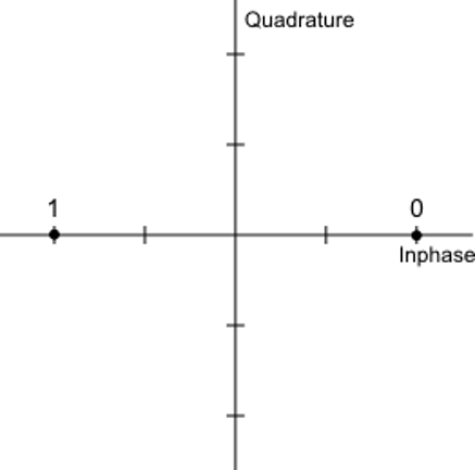
Figure 4. Binary Phase Shift Keying (BPSK) uses two phases for encoding the modulation.
Quadrature phase-shift keying (QPSK) uses four different phases of the signal to represent four different logic states (Figure 5). Each logic state can represent two bits of information, improving our data throughput. Again, the amplitude of the vector remains constant and only the phase changes.
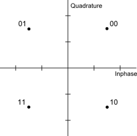
Figure 5. Quadrature phase-shift keying (QPSK) uses phase shiting to represent combinations of bits
Quadrature Amplitude Modulation (QAM) uses both amplitude and phase modulation to determine the modulation state. For example, 16-state QAM (Figure 6), provides 16 different logic states with unique amplitude and phase values. Now we see why the term constellation diagram is used, because the logic states start to look like a pattern of stars in the sky. This method can encode 4 bits of data for each logic state. For simplicity, these logic values are not shown in the figure, but they would sequence through 0000, 0001, 0010, up to 1111.
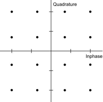
Figure 6. 16-QAM Modulation uses 16 combinations of amplitude and phase to represent four bits (16 combinations).
Higher-order QAM systems are used, including 64-QAM, 256-QAM and 1024-QAM. Increasing the number of amplitude/phase states increases the number of bits that can be encoded which dramatically increases the throughput of the modulation system. The tradeoff is a degradation in noise performance: the more unique states that are encoded, the closer they are together in amplitude and phase. Any noise present in the system is more likely to introduce a demodulation error.
We briefly mentioned FSK as a modulation type, which does get used in wireless systems. However, due to its higher spectral efficiency, QAM has largely replaced FSK in mobile wireless applications.
Continue to Digital modulation basics, part 2: QAM and EVM.
References
- Spectrum and Network Measurements (2nd Edition), Robert A. Witte, Chapter 6, SciTech Publishing, 2014.
- “Digital Modulation in Communications Systems- An Introduction,” Application Note, Publication Number, Keysight Technologies, 2014. http://literature.cdn.keysight.com/litweb/pdf/5965-7160E.pdf
Bob Witte is President of Signal Blue LLC, a technology consulting company. Bob has held many positions in R&D, technology planning, strategic planning, and manufacturing for Keysight Technologies, Agilent Technologies and Hewlett-Packard Company. Inside, he is just an engineer that loves to see innovative products solve real customer problems. Bob is the author of two books on test and measurement instrumentation: Electronic Test Instruments (2nd Edition) and Spectrum and Network Measurements (2nd Edition). See http://www.electronic-measurement.com for more information.

Very simple very nice