The 2022 Test and Measurement Handbook highlights test equipment techniques for today’s and tomorrow’s communications. Download your copy or read it online.
 Everything needs testing and that’s certainly true for wireless communications. EE World’s newly released Test & Measurement Handbook includes some 17 articles, of which three focus on wireless communications test. Click on the cover image to read online or download.
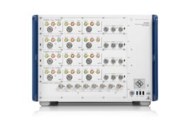
In “5G test equipment goes mainstream,” (page 26, PDF page 28)
Engineers from Rohde & Schwarz explain testing 5G’s RF devices in production. The article focuses on error-vector magnitude (EVM), the measure of amplitude/phase locations in a constellation diagram compared to their ideal locations. EVM is generally expressed in percent or in dB, as the equation below shows.
The difference between testing RF circuits in 5G, as opposed to previous generations, comes from 5G’s use of mmWave signals. Those currently fall between 24 GHz and 60 GHz. The article points a signal’s mean (RMS) power and peak power, which can vary greatly depending on the modulation used. For QPSK signals, the values are equal because there are just two modulation levels. That breaks down when QAM signals come into play, and 5G can use up to 1024 QAM, through 64 QAM and 256 QAM are more common.
“Exceeding 100 Gbps with a sub-terahertz 6G testbed” (page 32, PDF 34) by Greg Jue of Keysight Technologies looks at techniques to increase data throughput. One such method is to use higher-order modulation such as 64 QAM and higher. Another involves higher frequencies, over 100 GHz. The author describes Keysight’s H-Band (220 GHz to 330 Hz) testbed and the equipment it comprises. It describes the measurements that the testbed makes, which include constellation diagrams at 310 GHz using a 30 GHz channel bandwidth.

This test bed, which covers 220 GHz to 330 GHz, consists of an arbitrary waveform generator, a vector signal generator, and an upconverter.
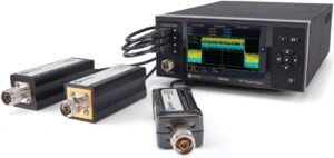
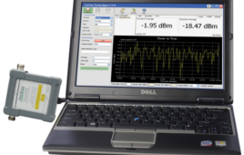
In “Key considerations for RF power measurement equipment” (page 36, PDF 38) Boonton’s Bob Buxton looks at the techniques engineers use to measure RF power.
- Diode detector: The RF signal is rectified or “detected” to yield a dc voltage proportional to the signal amplitude.
- Receiver: A tuned circuit receives the signal to allow measurement of its amplitude component.
- RF sampling: The RF signal is treated as a
baseband ac signal and is directly digitized.
Buxton uses a Q&A style to answer questions such as that ask what type of RF power sensor you should use for measuring average or pulsed power.


5G