Orthogonal frequency-division multiplexing has become the standard modulation format for 5G New Radio. Lean how OFDM works and how it’s used.
Orthogonal Frequency Division Multiplexing (OFDM) is an efficient modulation format used in modern wireless communication systems including 5G. OFDM combines the benefits of Quadrature Amplitude Modulation (QAM) and Frequency Division Multiplexing (FDM) to produce a high-data-rate communication system. QAM refers to a variety of specific modulation types: BPSK (Binary Phase Shift Keying), QPSK (Quadrature Phase Shift Keying), 16QAM (16-state QAM), 64QAM (64-state QAM), etc. Refer to Refs. 1 and 2 for more information on QAM.
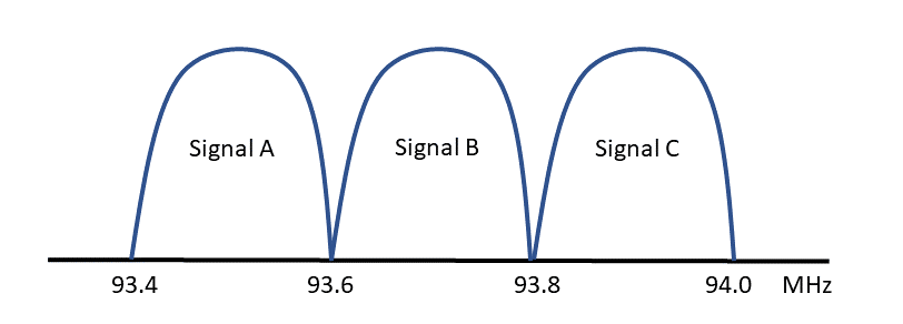
FDM is simply the idea that multiple communication channels can coexist by designating a slice of frequency spectrum for each channel. A common example of this is FM broadcast radio: the overall (US) frequency allocation is 87.8 MHz to 108 MHz, divided into channels that are 0.2 MHz wide (Figure 1). FDM frequency allocations must not overlap and often have guard bands between the channels to minimize adjacent channel interference.
OFDM
The basic concept of OFDM was first proposed by R. W. Chang [see Ref 3], recognizing that bandlimited orthogonal signals can be combined with significant overlap while avoiding interchannel interference. Using OFDM, we can create an array of subcarriers that all work together to transmit information over a range of frequencies.
These subcarriers must be orthogonal functions. The precise mathematical definition for orthogonality between two functions is that the integral of their product over the designated time interval is zero. More loosely, we can consider orthogonal functions to be statistically unrelated.
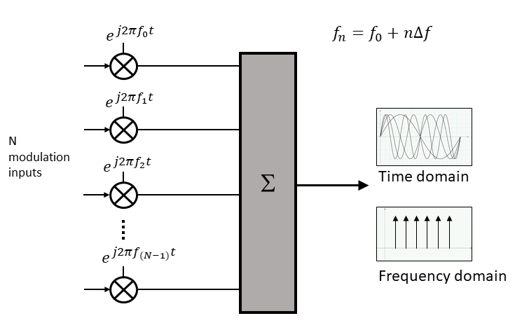
Figure 2 shows how N equally-spaced subcarriers can be combined to form an array of parallel signals. Each of the subcarriers is modulated using QAM. These modulated subcarriers can be used to support independent baseband signals but more typically they are combined to provide the maximum data throughput for one stream of data.
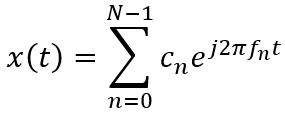
We can represent these subcarriers mathematically, using the complex form consistent with the use of QAM.
![]() The equations above are continuous functions and OFDM systems have been implemented in analog form. However, modern systems are almost all digital, taking advantage of the latest semiconductor process nodes and digital signal processing.
The equations above are continuous functions and OFDM systems have been implemented in analog form. However, modern systems are almost all digital, taking advantage of the latest semiconductor process nodes and digital signal processing.
Modern OFDM systems use subcarriers that exist in discrete (sampled) form with a sample rate of:
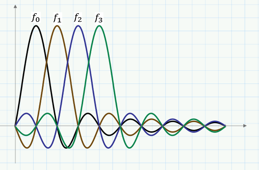
 For simplicity, Figure 3 shows just four unmodulated subcarriers in the time domain. The black trace is f0 and the other traces are higher frequency subcarriers, spaced at multiples of ∆f.
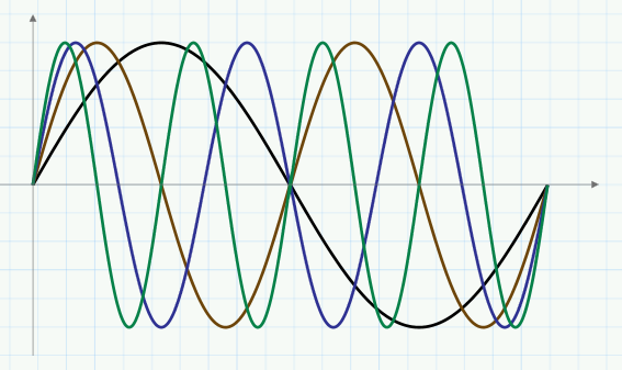
Figure 3. This OFDM signal contains four carriers spaced apart by f corresponding to f0, f1, f2, f3.
Figure 4 plots these same subcarriers in the frequency domain, shown with some modulation bandwidth to indicate the overlap between subcarriers. The subcarriers are orthogonal to each other and will exhibit minimal interference to the other subcarriers, resulting in efficient use of bandwidth. Note that the amplitude of each subcarrier crosses zero at the center of other subcarriers, minimizing adjacent subcarrier impact.
Figure 5 shows a basic block diagram of a complete end-to-end OFDM system consisting of a transmitter and receiver. The bit stream enters the system on the left of the diagram. As typical, this single bit stream is demultiplexed (DEMUX) into smaller bit streams that are fed to the individual QAM modulators for each of the N subcarriers.
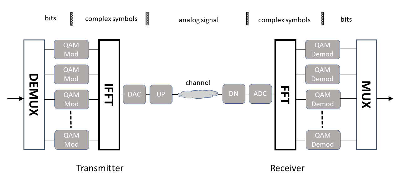
Figure 5. A complete OFDM system includes a transmitter (left) and receiver (right). Power amplifier in transmitter not shown.
A key enabler for OFDM is the use of the Inverse Fast Fourier Transform (IFFT) to efficiently create the time domain waveform from the array of modulated subcarriers. The resulting OFDM signal is in digital form which drives the Digital-to-Analog Converter (DAC) which converts it to an analog signal. This baseband signal is usually up-converted (UP) to a higher frequency (and perhaps amplified) before being transmitted via the over-the-air channel.
At the receiver, the process is reversed. An analog downconverter (DN) shifts the OFDM signal back to baseband. The Analog-to-Digital Converter (ADC) converts the signal to digital form and passes it on to the FFT block. The FFT block transforms the time domain signal back to the array of subcarriers carrying QAM modulation, in the frequency domain. The QAM demodulators reproduce the bit stream from each subcarrier, which is then multiplexed (MUX) to recreate the original single data stream.
The big ideas here are 1) combining many QAM subcarriers to create a wide-bandwidth system and 2) the use of the FFT and IFFT to efficiently transform those subcarriers into a single wireless signal. A range of QAM modulation can be used, starting with BPSK (one bit per symbol) up to 256QAM (8 bits per symbol). Combining this with the use of many subcarriers (perhaps 4096) results in very high data rates.
Time Plus Frequency
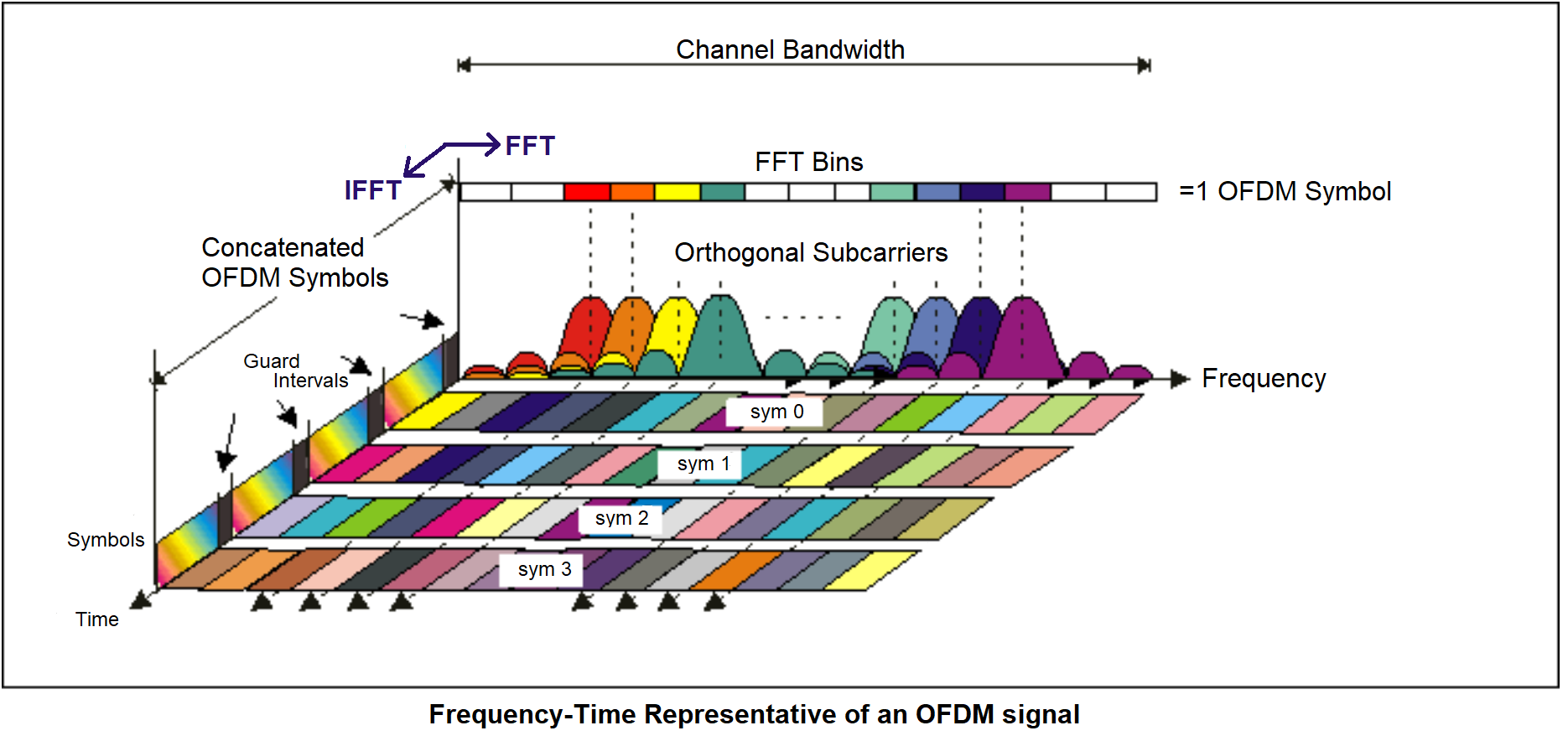
Figure 6 shows the time plus frequency domain view of an OFDM signal. The horizontal axis is frequency and the vertical axis is amplitude. The third axis, coming out of the page, is time, allowing us to see the OFDM signal progressing from the back of the graph to the front. Each symbol shown in the figure is one set of OFDM subcarriers transmitted down the channel.
Note the inclusion of a guard interval to provide some time separation between symbols. This is a simple method to prevent multipath propagation in the channel from causing interference between symbols. A more advanced method inserts a Cyclic Prefix (CP) into the guard interval, resulting in a form of OFDM called CP-OFDM. The CP is created by copying the last part of the IFFT record and appending it to the beginning of the record, acting as the guard interval.
Uses of OFDM
The wireless LAN standard, IEEE 802.11a, was one of the first standards to employ OFDM. This standard uses 64 subcarriers spaced by 312 kHz, which can be modulated with several different QAM variations: Binary Phase Shift Keying (BPSK), Quadrature Phase Shift Keying (QPSK), 16QAM or 64QAM.
Mobile wireless systems employ OFDM to achieve high bandwidth channels. Existing 4G (LTE) mobile wireless uses OFDM for the downlink (base station to mobile device), with a fixed subcarrier spacing of 15 kHz. The modulation on the subcarriers can be QPSK, 16QAM or 64QAM.
The 5G New Radio (NR) standard uses OFDM on both the uplink and downlink. The NR specification is designed with a high degree of flexibility to cover a diverse set of applications. The carrier spacing is flexible (15 kHz, 30 kHz, 60 kHz, 120 kHz, 240 kHz, 480 kHz) with up to 3300 subcarriers. The subcarrier modulation can be QPSK, 16QAM, 64QAM or 256QAM. For more information on the 5G physical layer, see Ref 6.
References
- “Digital modulation basics, part 1”, Bob Witte, Feb. 20, 2020, https://www.5gtechnologyworld.com/digital-modulation-basics-part-1/.
- “Digital modulation basics, part 2: QAM and EVM”, Bob Witte, Mar. 4, 2020, https://www.5gtechnologyworld.com/digital-modulation-basics-part-2-qam-and-evm/, .
- “The History of Orthogonal Frequency-Division Multiplexing”, Stephen B. Weinstein, IEEE Communications Magazine, November 2009 https://ieeexplore.ieee.org/document/5307460
- “Concepts of Orthogonal Frequency Division Multiplexing (OFDM) and 802.11 WLAN”, Keysight Technologies web page, http://rfmw.em.keysight.com/wireless/helpfiles/89600B/WebHelp/Subsystems/wlan-ofdm/Content/ofdm_basicprinciplesoverview.htm
- “Digital Modulation in Communications Systems- An Introduction,” Application Note, Publication Number, Keysight Technologies, 2014. http://literature.cdn.keysight.com/litweb/pdf/5965-7160E.pdf
- “Understanding the 5G NR Physical Layer,” Presentation, Javier Campos, Keysight Technologies, November 2017, https://www.keysight.com/upload/cmc_upload/All/Understanding_the_5G_NR_Physical_Layer.pdf
 Bob Witte is President of Signal Blue LLC, a technology consulting company. Bob has held many positions in R&D, technology planning, strategic planning, and manufacturing for Keysight Technologies, Agilent Technologies and Hewlett-Packard Company. Inside, he is just an engineer that loves to see innovative products solve real customer problems. Bob is the author of two books on test and measurement instrumentation: Electronic Test Instruments (2nd Edition) and Spectrum and Network Measurements (2nd Edition).



Hi Bob:
I read your nice little note on OFDM and I have a question.
I can’t find anywhere in the literature what frequencies are used for the N OFDM modulators, fn = f0 + n𝚫f (n=0, 1, 2 N-1). In the case of 4G are the frequencies in the allocated bands, from about 800 MHz up to several GHz? If that’s the case, is the sum of all the N modulated analog signals upconverted to a higher RF signal before transmission through the channel?
Your answer would be appreciated. Thank you, and you may reply directly to my personal email address:
h2@alum.mit.edu.
In Figure 5, the OFDM signal is assembled at baseband and then upconverted to the desired channel frequency. The figure shows just a simple upconverter box but, of course, it will usually be much more complicated. LTE channel bandwidth will vary depending on implementation but the widest common bandwidth is 20 MHz.
This article goes into more detail about how the OFDM signal relates to channel bandwidth:
https://home.zhaw.ch/kunr/NTM1/literatur/LTE%20in%20a%20Nutshell%20-%20Physical%20Layer.pdf
It confused me initially when article said OFDM is a modulation technique. While you rightly go on to explain subcarrier is the one that’s modulated, i believe OFDM is simply a multiplexing idea with orthogonal frequencies.
Good point.
OFDM multiplexes many subcarriers together and that’s the main benefit of the technique.
The article is brilliant ! Thanks !
Thanks for reading it and commenting!
As we go to shorter wavelengths will passing through any media reduce signal orthogonality enough to degrade signal levels?
Ted,
Good question and I am not completely sure of the answer.
In general, OFDM is very robust in dealing with channel imperfections. For example, it handles multipath distortion well, which is common in mobile wireless systems. Based on the literature I’ve read, the concerns around going higher in frequency are mainly due to increased channel loss, not loss of orthogonality.
Bob
Can you please explain the relationship between subcarrier spacing and symbol duration? I understand that symbol time is the reciprocal of the subcarrier spacing, and that larger sub-carrier spacing therefore yields a shorter symbol/slot duration (which enables, for example, both eMBB and URLLC services in 5G), but I don’t understand exactly what the basis of that relationship is. Thanks.
Lewis,
I think you just wondering what causes the symbol time to be the reciprocal of the subcarrier spacing. The short answer is that it is a characteristic of the FFT.
Here’s the slightly longer answer:
The time duration of a symbol will be the time associated with N samples: N (1/fs) = N/fs.
where fs is the sample rate.
The spacing between subcarriers is also tied to fs and the number of samples N. Again, this is a characteristic of the FFT. The N subcarriers in the frequency domain are spread evenly across the fs frequency range. That gives us the subcarrier spacing of fs/N.
So the symbol time is N/fs, which is the reciprocal of fs/N.
Thanks Bob for the clear explanations.
From Figure 3 to figure 4:
I assume an iFFT generates exact tones with single nonzero sample and that when we talk about lobes we mean the frequency domain in real world (after DAC).
The lobes of figure 4 may also occur before DAC if we consider phase discontinuities of a stream of symbols.
Am I right?
The lobes shown in Figure 4 are the result of the iFFT and occur before the DAC. Mathematically, (sin x)/x or sinc functions create these lobes. The figures in Ref 4 may be helpful.
Of course, the DAC may also introduce additional frequency components.
Bob.
great article particularly to me as an aerospace avionics engineer with a continuing interest in the airborne FMCW Radio Altimeter interference potential . I did not appreciate the fact that 5G uses OFDM both from the base station and the user device unlike the one way 4G.
Whilst the aerospace community likes devices to be “OFF” or aeroplane mode in flight this is commonly not the case and it is almost impossible to “police” I would like to see some extensive testing to ascertain the interference potential prior to full implementation of 5G. Current discussion seems concentrated on the ground stations with little consideration of the PED activity.
Robert,
Thanks for your comment. We just posted an article on the altimeter issue. See https://www.5gtechnologyworld.com/5g-altimeter-interference-aviation-versus-telecoms/
Which modulation scheme can be used at 5.1 GHz to 10 GHz applications
In general, any modulation scheme can be used across a wide variety of frequencies. Modulation type is usually driven by the application, the available bandwidth, and regulatory requirements.
5G spectrum is divided into Frequency Range 1 and 2 (FR1 and FR2). FR1 is below 6 GHz and FR2 is ~24 to 52 GHz. So the 5G modulation methods may be used in those frequency ranges. Also, Wi-Fi 4, 5, and 6 use the 5 GHz band with OFDM and a variety of modulation types. See https://www.eeworldonline.com/ofdma-improves-spectrum-use-in-wi-fi-6/
The FCC frequency allocations between 5 GHz and 10 GHz include radiolocation (RADAR) and satellite communications. Satellite comms are usually wideband digital signals and may use OFDM. See https://blogs.keysight.com/blogs/tech/rfmw.entry.html/2020/08/24/modulation_schemesf-6MpZ.html
“that bandlimited orthogonal signals can be combined with significant overlap while avoiding interchannel interference.”
Dear sir,
Here what is the meaning of avoiding interchannel interference (How)